I’m getting ready to install several electric gizmos on my Honda Pacific Coast. To prepare I decided to install an auxiliary fuse block. The local marine supply shop happened to have a Blue Sea Systems ST Blade Fuse Block (PN: 5025). I bought it and brought it home. This specific unit has both a positive and a negative block. The negative is simply a large grounding plate while the positive side has six independent fuses. On several websites I have seen people using various Blue Sea Systems fuse blocks.
Safety Warning: I’m sure I don’t have to tell you but anything you do or don’t do due to this page, the photos on the page, the text, or anything else that in any way involves me is done at your own risk. Doing these modifications voids any and all warranties on any and all devices that you own. This can be a fire hazard, can cause death and dismemberment, can make your significant other leave you, and might make you become an alcoholic. This worked for me but might not work for you. Your mileage may vary. Proceed at your own risk!
Synopsis: I sawed a fuse block in half, applied liberal quantities of silicon RTV, and stuck the two halves into the trunk of my bike. It’s not super pretty but it works and was done with the parts I had on hand. You will need a Blue Sea Systems fuse block P/N 5025. It costs about $40. You will also need silicon RTV, extra blade fuses, 14 gauge or larger wire to run between the battery and the fuse block (2 or 3 feet of black and of red), an automotive relay and wire harness (under $20 at your local auto parts store) if you want the power to be killed while your bike is off, various miscellaneous connectors and splices, and a hack saw. A flat file is optional.
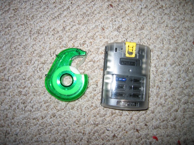
This is the unit straight out of the packaging. It comes with one 15 amp fuse and a plastic cover. I put a roll of tape next to it for size comparison. Ignore the red bits of wire insulation in the photo. My Roomba is going to be very busy vacuuming those bits up!
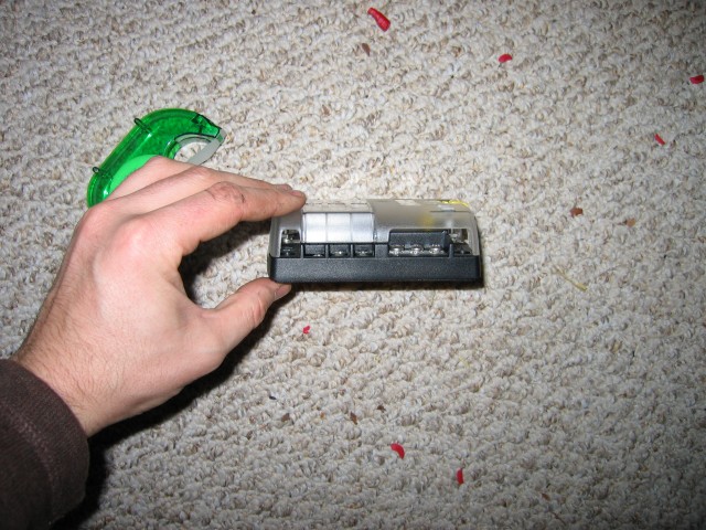
From the side. The right three screws are for ground wires while the left three are fused. This is mirrored on the other side. The wires that feed the positive and negative buses come in at the ends of the unit. With the plastic cover on, each feed wire can be placed either right, left, or straight out from the unit.
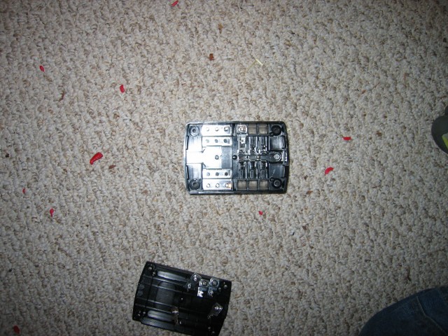
Being inquisitive, I took the unit apart to see what was inside. As you can see, the ground side (left) is just a big piece of metal (copper coated in tin or something along those lines that doesn’t rust in salt air). The right side contains the fuse blocks and is individually isolated. Being segregated into two sides like this will become important in another few photos.
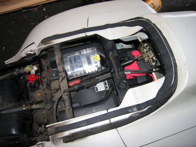
After looking around for a happy place to mount the fuse panel on the bike I decided to put it in the trunk area. Everywhere else I looked I either already had something, it wouldn’t fit, or I would never be able to change a fuse.
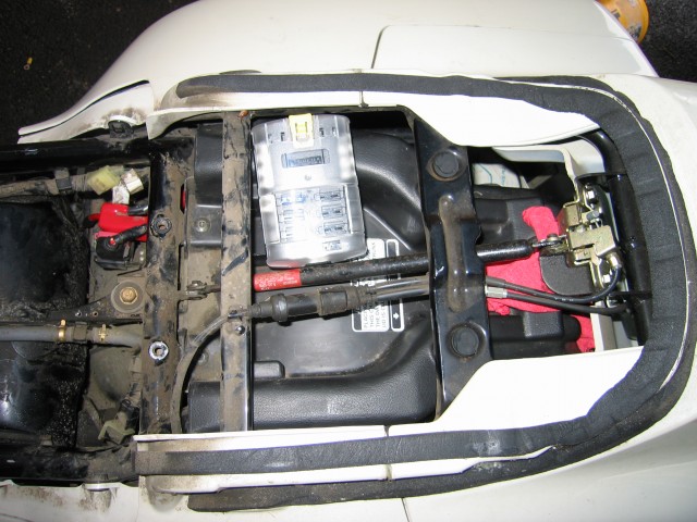
Hmm it doesn’t fit. However, looking at it in this position gave me an idea. What if I cut it in half and split the two sides on either side of the gas spring for the trunk lid? This looks like a good afternoon project!
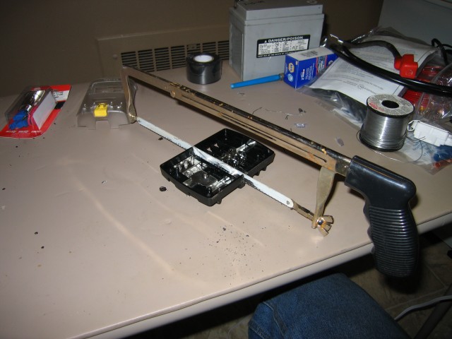
This poor table sure does take a beating. Yesterday I was soldering on it. Today I’m using a hacksaw. If my ex knew what would happen to it, she probably would have never let me borrow the table!
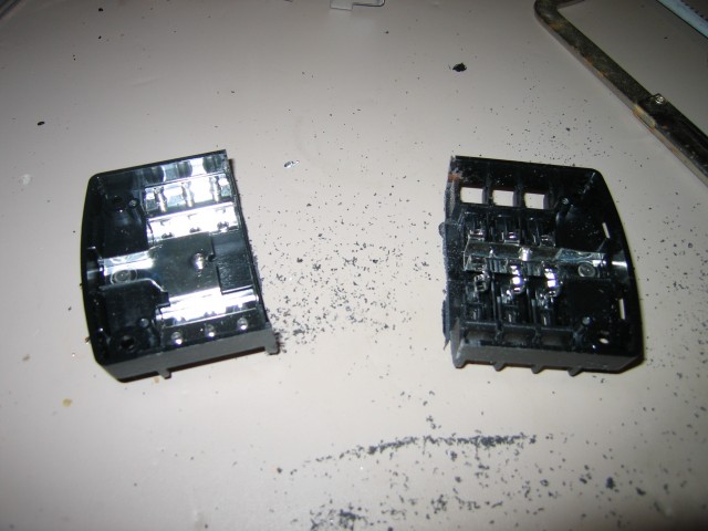
I cut down the center where there happened to be a natural saw-guide molded into the plastic. Pretty sure this voided my warranty and means I can’t return it if I decide I don’t like it.
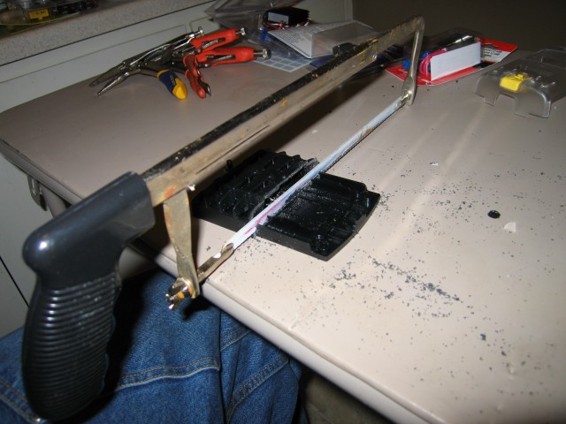
Cutting the bottom in twain. Without the bottom, the fused terminals wouldn’t stay put. Again there is a convenient set of guides to keep the saw going straight and true.
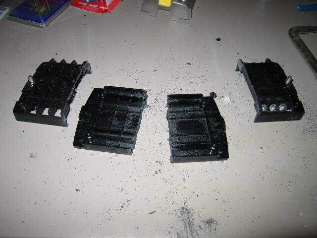
All the pieces cut apart.

I used a flat file to clean it up a little bit. If you aren’t bothered by rough edges, this step can be skipped. The only reason I did it was I figured I might want to sell this motorcycle someday in the distant future.
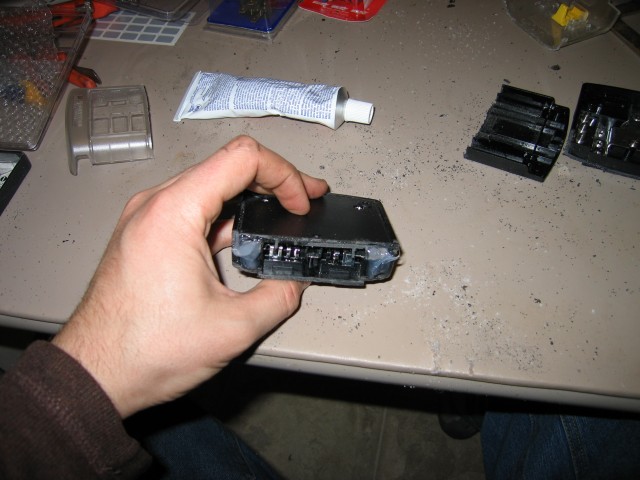
Next stop, Silicon RTV city! In case water ever gets in and tries to muck things up or some insects decide they need a warm little nest I decided to block up the cut ends of the two sides of the fuse block.
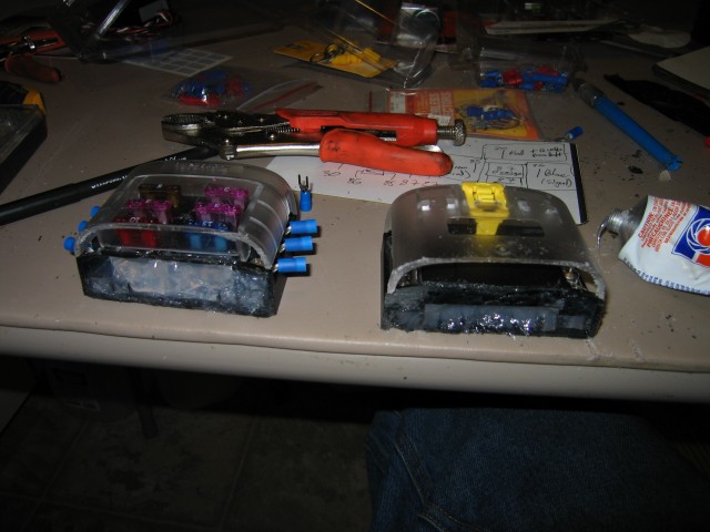
Lots of RTV filling up the spaces. I made sure to not inject the RTV in far enough to come in contact with the terminals. If that RTV got into the fuse blocks, they might not work correctly.
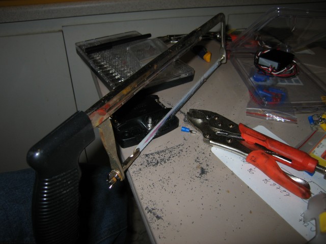
I did a test fit and found that the two halves still didn’t quite fit. Back to the hack saw! This time I trimmed off the corner on the negative buss block. The fused buss block required having the whole front edge hacksawed off. For some reason I didn’t take a picture of it. If you happen to actually try doing this crazy mod, do a few test fits and you’ll figure out what to do.
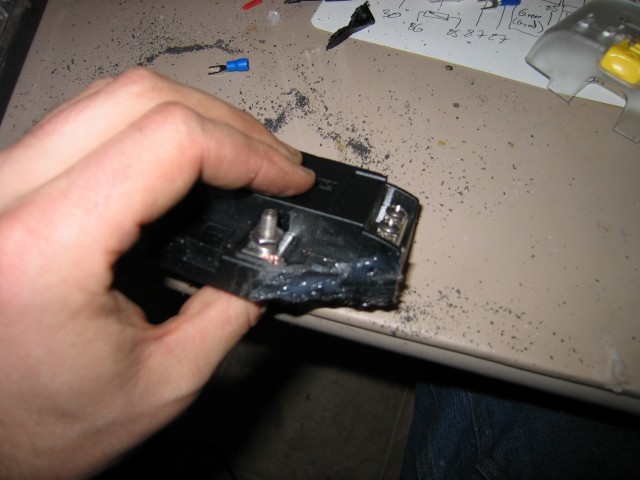
More RTV to keep the buggies out.
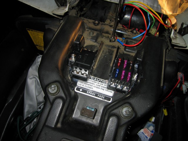
Fitting the two halves into the trunk compartment. I used a LOT of RTV to attach the buss block and fuse panel to the trunk plastic. You might want to use screws or some other form of adhesive. I just happened to have a tube of RTV at my disposal and wasn’t afraid to use it.
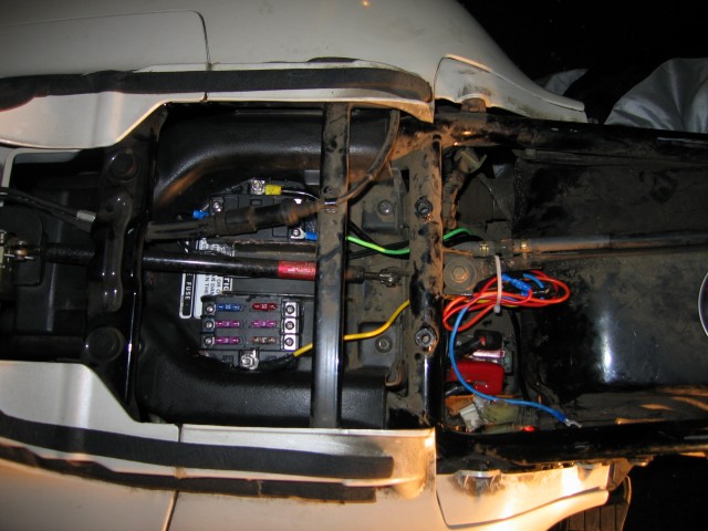
Looking down at the finished install with the trunk closed and the passenger seat removed for a better view. Both halves of the fuse block fit snugly on either side of the gas shock. I am running wires between the frame and the wheel well/fender plastic. My messy wiring and relay are zip-tied to the piece of metal that attaches between the frame and the gas tank. I purchased a cheap automotive relay and harness from the local auto parts store. Any auto parts store will have one for under $20. The fuse block has a fuse between it and the battery. It’s located down by the battery and is accessible when the trunk is open. I put a 30 amp fuse on the entire auxiliary fuse block because of the size of the wire I used and because if I’m using that much, I have a big, big problem.
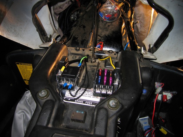
One final view of the completed installation. The wiring hadn’t been tidied up in this picture yet. It looks marginally neater now. All in all I am very happy with this modification. The only downside is that you lose the protective plastic cover. But with the trunk closed I’m not too worried about water dripping or splashing into the space. My passenger and driver seat both have plastic wrap installed to prevent leaks.
If you find these photos useful, do it yourself, have questions, or anything else, please drop me a comment below! Send me some photos of how you installed yours and I’ll put them on this page. And remember, YMMV.

I need to remove my battery from the PC800. Do you have any clue as to what all has to come off and how to get the battery out EASILY?
Thanks.
Lou
PS Looks like you did a great job with the fuse block. Congrats!
Lou,
If you don’t know about the group of PC riders on Yahoo already, check out http://www.pc800.net. Check out http://www.directcon.net/lcshepp/PC800SMPage2-2.html for a guide to removing body panels. This page gives the official Honda step-by-step to removing the battery. Also if you get on the IPCRC and search the files section, you will find (at the very bottom of the list) a file called “Tupperwear Removal Guide.” It has exactly what pieces of plastic to remove to get to the battery. I know in the past I’ve seen a file on the IPCRC somewhere that has a more direct procedure for getting the battery out. Can’t find it at the moment though. With a little Googling or if you post a question to the group, it should turn up.
Glad you liked the aux fuse block and happy riding!
How do I remove the front seat on an 1996 pc800?
Hi Stephan,
To remove the seat on any PC800 (1989-1998), do the following:
1) open the trunk
2) locate the two bolts holding the driver seat down (directly behind the seat)
3) undo those bolts and put them somewhere you won’t lose them
4) close the trunk part-way and slide the drivers seat back until the front of the seat and its catch can clear the faux tank area and be removed by being pulled forward
And that’s all there is to it!
By the by, if you aren’t aware of it already, you should join the IPCRC at pc800.net for the best help there is on PC800 questions. Also the PC800 shop manual at https://www.douglasvanbossuyt.com/honda-pacific-coast-pc800-service-manual/ is very useful as well.
Cheers!
Douglas
Hi Douglas,
My name is Glynn and i,m in Cape Town South Africa, I have a black and silver pc800 . Can you please tell me where the fuse box is and how I get to it. I removed the seat and found the main 30a fuse underneath it. My brake lights are not working and I need to check the fuses. I found the wiring diagram on the net but it doesn,t tell you where the fusebox is. Thank you kindly!
Best Regards
Glynn
Hi Glynn,
The main fuse block is behind the left side engine air exhaust vent. If you are sitting on the bike, it is behind the plastic just in front of your left knee. This shows where it is: https://www.douglasvanbossuyt.com/honda-pacific-coast-pc800-service-manual/pc800-service-manual-chapter-18-lights-meters-switches/page-18-2/
The whole service manual is available online at: https://www.douglasvanbossuyt.com/honda-pacific-coast-pc800-service-manual/ Also if you aren’t a member yet, you should join the IPCRC Forum at pc800.net. It is by far the best place to get information on how to repair and keep your PC800 riding.
Hope that helps!
Cheers,
Douglas
You have a great site with much helpful stuff. But your pix of Ch-ch are very sad. I spent a lot of time there while flying for Deep Freeze. Did you ever make it to the Antarctic museum there? I hear it’s pretty good. Did you ever make it to Queenstown or Arrowtown and Lindis Pass? Beautiful places. Cheers. Bruce on Planet Battle Ground. Klatu Birada Nikto..
Hi Bruce!
I never made it to the museum in Christchurch. Too much rumbling of the earth at the time. I think it actually was closed due to earthquake damage. I was there between the two big earthquakes. We made it to Queenstown. Didn’t go to Lindis Pass or Arrowtown but we did come over from Franz Joseph to Wanaka. I’m glad the site is a help for you!
Cheers!
Douglas