10am: After fighting with a surging idle yesterday, I re-evaluated where my MAP sensor was getting its vacuum data. Yesterday I had changed the placement of the MAP sensor’s vacuum pickup from inside the front of the airbox near the IAT sensor to the combination of the front and rear cylinder vacuum pickups where the venturis are located below the butterfly valve plates on the throttle body. This was giving me an incredibly fluxuating MAP reading by up to 20KPa. Now I have moved the MAP vacuum pickup back inside the airbox and close to both intake runner trumpets. Hopefully this will help matters and give me a monitorable vacuum source that will both change when it should based upon engine load and also not have such wild fluctuations.
I also verified that Injector 1 wiring goes to the front cylinder and Injector 2 wiring goes to the rear cylinder. While I had the airbox off, I also confirmed that I have a good airtight seal in the throttle bodies. Oh, and I also rewired the TPS so that it doesn’t read upside down anymore. I had miswired the high and low sides before although that didn’t seem to make a difference to the MicroSquirt. Now I’m waiting for the RTV goop to dry in the airbox before I put it all back together and try firing up the bike again.
While I’m waiting, I’ll ruminate a bit on future spark control for the bike. Based on what I’ve deduced from the diagrams of the PC800 pulse generator wheel and the MicroSquirt V2 information (I have a MicroSquirt from circa May 2011 which means it is a V2), I believe that I can 1) get an adequate signal from the stock hall sensors and pulse generator wheel and 2) directly drive the spark generators on the bike. One problem I might encounter is that each coil drives two spark plugs on the PC800. The information on my MicroSquirt says that I should only be driving one coil and one spark plug per wire on the bike. Maybe that’s a problem… maybe not. I do know though that the spark generators on the PC800 only have two wires going to them. One wire is +12V and the other goes to the stock ignition control module where it is grounded to charge the coil and then I believe is let float to discharge the coil. The ignition and fuel only have a 10 amp fuse on the stock PC800 between them so I believe that the two spark generators are well below 7.5 amps each. Once I have a stable fuel map and whatnot, I think I am going to embark on controlling spark with the MicroSquirt as well.
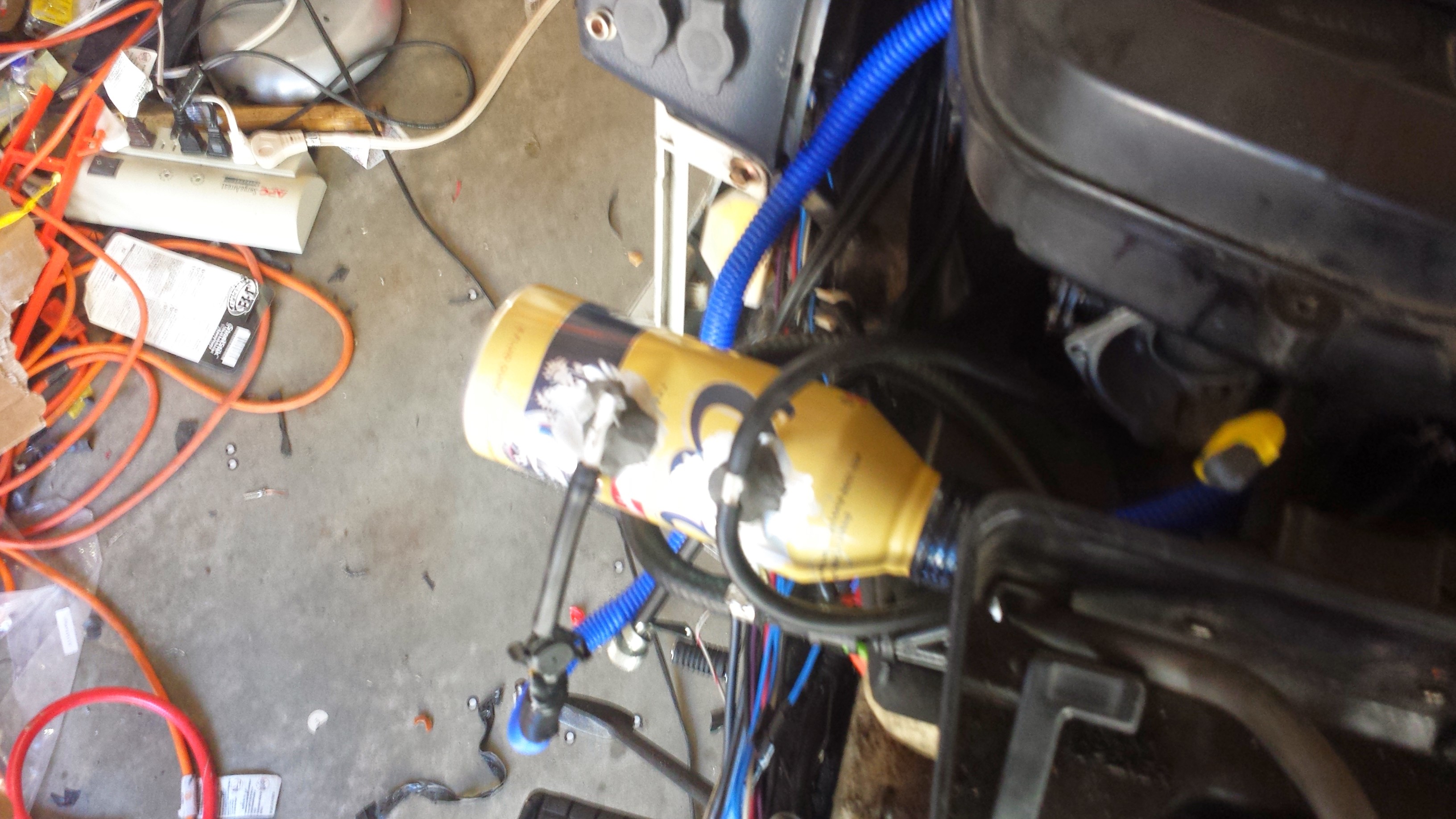
Noon: After much futzing around, I ended up using the Coors 16 ounce screw top beer can that I had originally planned for an oil catch from the crankcase breather hose (don’t need that anymore since I’ve gone back to the stock air box) to make a vacuum surge tank. I tried taking MAP vacuum from the air box again but it just wasn’t working. Now I have MAP running from the two vacuum ports on the throttle body via the beer can surge tank. I’m getting nice, stable, and reasonable MAP readings now.
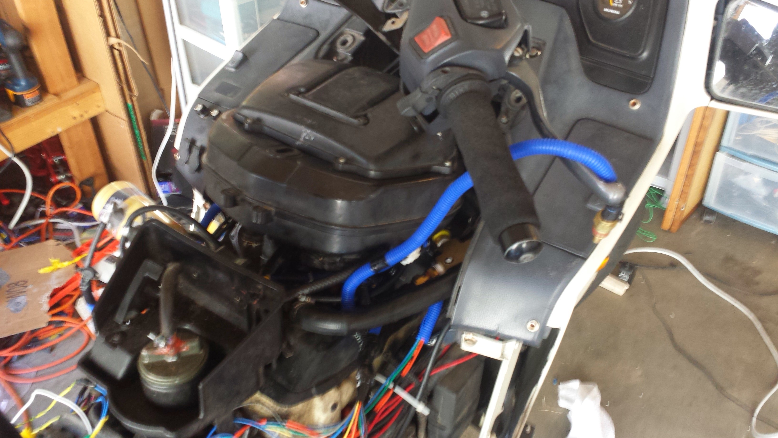
My next problem is saturation of the IAT sensor. I placed it on the bottom of the air box right over the engine. As anyone with a PC800 can tell you, the space around the air box really roasts regardless of if the cover is on or not. I am moving the IAT to be in the ambient air stream now and take data from somewhere more in line with the actual temperature of the air the engine is receiving.
1pm: I moved the sensor to be in free air and now I am getting realistic readings from that. However, that didn’t fix my idle problem. I’m still getting either very high idle (~3500RPM) or very lean AFR (~16-17). I then decided to remove the air box to see what happens. Lo and behold, the problem is exactly the same. Next, I tried closing up the air intake stream using some plastic lids. The more I closed the stream, the more the idle came down and the more the AFR started correcting itself until I got to the point where I had 1100 RPM and 13.5 AFR which is pretty good considering the VE table I’m using is absolute garbage and a complete guess on my part.
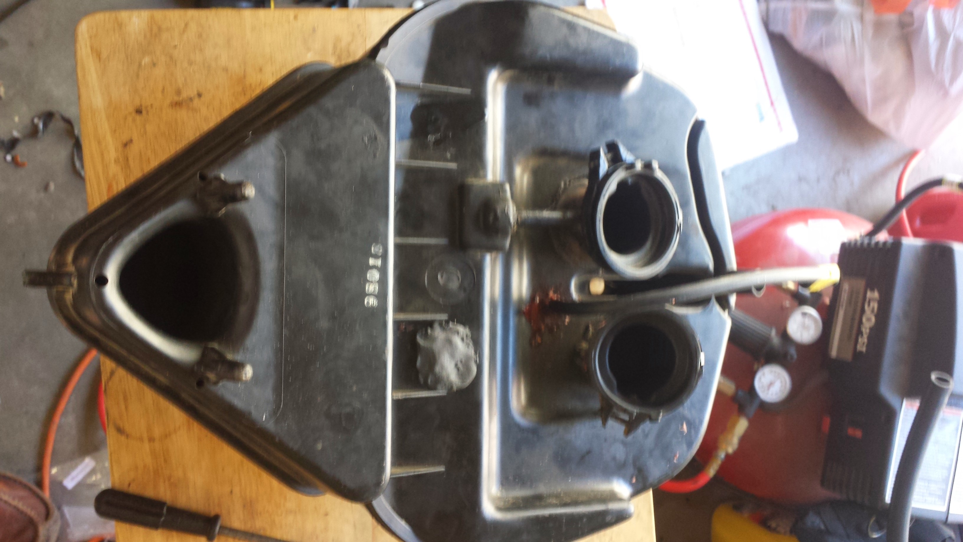
I think this means that the PC800 carbs when turned into throttle bodies let too much air through. I’ve gone back through and checked for leaks everywhere but there are none. Everything is sealed as it should be. The cross sectional area of the PC800 carbs where air can go through (ignoring the butterfly valves) is about 2.66 square inches across both cylinders. I calculated that number as follows:
pi * (diameter of one cylinder intake / 2)^2 = area of one cylinder intake
area of one cylinder intake * 2 = area of all intakes
sqrt(area of all intakes ÷ pi) * 2 = diameter of all intakes
And for the PC800, this is:
pi * (1.3 inches / 2)^2 = 1.327 square inches
1.327 square inches * 2 = 2.66 square inches
sqrt(2.66 square inches ÷ pi) * 2 = 1.84 inches for the diameter of all intakes
For comparison, on the VT1300CXA, the area of the throttle body is only 1.65 square inches (the diameter is 1.45 inches for those who want to do the math). Looking at the butterfly valves on the PC800 carbs versus the VT1300CXA throttle body, it appears the VT1300CXA seals a little more than the PC800 does as well. Is that enough to really make a difference? I don’t know but I’m guessing it might be…
At this point, I’m trying to decide what I could do to rectify this problem, if it really is a problem. I could try to hack together a way for the VT1300CXA throttle body (not the intake runners and injectors) to mate with the PC800 throttle body and remove the butterfly valves from the PC800. I could try to put in some sort of restriction on the air intake for the PC800 although that would probably starve the engine for air at high loads and high RPMs.
2pm: During lunch I thought about my problem more deeply. In looking through the excellent Performance Fuel Injection Systems book written by the guys at DIY Auto Tune, I found some information in the fuel delivery section of the book (page 21 in the first edition) on how to calculate a proper throttle body size. The formula for the cubic feet per minute is:
(maximum RPM * VE * engine displacement in cubic inches) ÷ 3456 = cubic feet per minute
I don’t know what volumetric efficiency will be on the PC800 but I’m going to guess it’s about 85%. The engine displacement for the PC800 is 800cc or 48.8 cubic inches.
On the PC800, the formula looks like:
(7500 * .85 * 48.8) ÷ 3456 = 90 CFM
Next, the Performance Fuel Injection Systems book tells me to convert the cubic feet per minute calculation I just did into a maximum throttle body area with the following formula:
(CFM * 2.4) ÷ 300 feet per second = maximum area of throttle body (square inches)
For the PC800, that formula is:
(90 * 2.4) ÷ 300 = 0.72 square inches
Converting this into a diameter using this formula:
2 * sqrt(Area ÷ pi) = diameter
Using that formula, we get a total effective diameter of:
2 * (sqrt(0.72 ÷ pi) = 0.957 inches
That is much different than the 1.84 inch effective diameter of all intakes for the PC800 throttle body that I produced from the PC800 carbs. I double-checked all of this with the simple calculations that can be done on this page and came back with 1.2 inch effective diameter. Close enough, especially since these formulas are most likely all empirically derived rather than based on any sort of fundamental theory.
I suspect that the slides in the PC800 carbs block a large amount of airflow at low RPM and open up more at high RPM based upon the vacuum bellows that they attach to. In effect, the slides are almost like a RPM-actuated damper valve found on some of the higher end V-twin muscle bikes put out by Honda and Yamaha. Interesting!
For the PC800 carbs to work as a throttle body, I would need to reduce the overall intake diameter to just under 1 inch. I believe that my options are either to block part of the flow at the top of the PC800 carbs-turned-into-throttle-bodies or block the flow at the air box intake. The air box intake will be a bit tricky as it is a triangular shape rather than a circle or square. However, if I can reduce the area out at the end of the air box, then I could pipe in the IACV into the air box. Otherwise I might have to drill new holes in the PC800 carbs below the butterfly valves in order to pipe in IACV air.
2:30pm: I did a test where I took off the top-most piece of the air box that is removable (rectangular-looking thing) and blocked air flow with my hand. By blocking air flow there, I was able to change the speed of the engine and the AFR as well, even with my bad VE table. I’m pretty sure this means that I need to constrict the amount of airflow that the throttle bodies receive. One potential problem I observed with restricting airflow where I did is that the air box actually started to collapse in on itself a little bit due to the vacuum that started building. That isn’t particularly desirable!

What I might try doing is getting some relatively thick tin or sheet metal and cutting it into circles that could slip in above the PC800 carbs/throttle bodies and below the air box connector. I would drill holes in the sheet metal of the correct diameter to allow the proper amount of air through. That just might work.
Now it’s time to go down to the river for some afternoon summer tubing. I’ll come back to this project hopefully later tonight. I’m pretty sure I have some sheet metal sitting around my garage somewhere…