Adding Vacuum Taps to a PC800 Throttle Body

20141207_151937

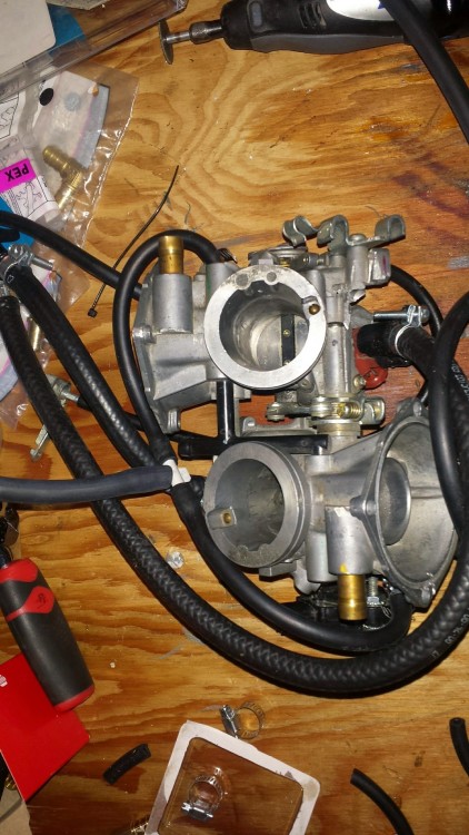
I did some work today to add a second set of vacuum taps to the Honda Pacific Coast PC800 carburetor that I have modified into fuel injection throttle bodies as part of my long-running fuel injection conversion project.  In this photo you can see two metal pipes penetrating the lower portions of the throttle bodies.  These pipe taps will act as vacuum taps.  I am going to hook either the Manifold Air Pressure (MAP) sensor or an Idle Air Control (IAC) valve to these taps.  The other existing factory-installed taps will be used for the MAP or IAC that isn’t plugged into the new set of taps.


20141209_161503

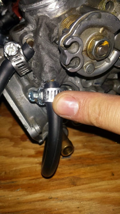
Here’s the finished view with vacuum hose hooked to the new taps and the new tapx shaved flush in the throttle bodies.

20141209_161514

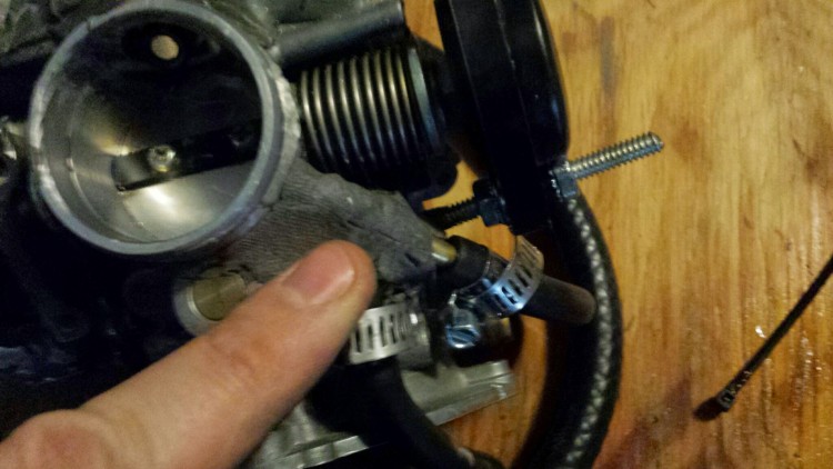
My finger is pointing to the new tap.

20141209_161528 20141209_161638

All in all, it was a pretty clean installation.  I used JB Weld to hold everything together.  Hopefully the 10% ethanol gas that we get everywhere in the USA won’t someday degrade all of the JB Weld that holds together the throttle bodies.
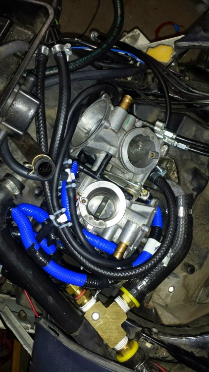
20141209_173306The throttle bodies installed on the bike.  Lots of hoses and wires running everywhere to make this bike come alive!  Up next is figuring out how to make the MAP sensor not flutter all over the place (vacuum reservoir) and finally figuring out how to do proper idle air control using an IAC that works with my existing MicroSquirt setup.  The engine really needs IAC so that it will properly start when the engine is cold.

 

How to break a MicroSquirt

20140829_142845

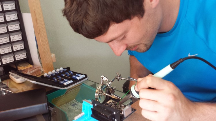
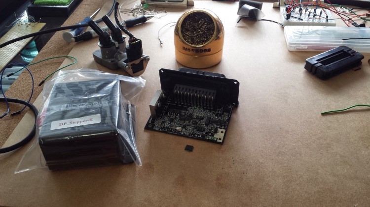
Over the weekend I went out to Oregon for a wedding.  While I was there, I visited Brent and his little home electronics lab to see about modifying my MicroSquirt to be able to run a stepper motor for idle air control.  Previously I had determined exactly what modifications were needed.  Since Brent is more skilled with all things electronic, I asked him to do the modifications.

20140829_143528

As Brent was working on connecting wires to pins 9, 10, and 12 on the MicroSquirt CPU (a MCS12C64 Freescale chip), disaster struck.

20140829_152858

We ended up with a broken pin on the CPU and a lifted trace on pins 9 and 10.  The lifted traces aren’t such a big deal but the broken pin on the CPU is too small to fix with the tools we have available to us.  I contacted Matt at DIY Auto Tune for his thoughts and to see if we could possibly buy a new chip from him to put onto the board.  Alas, we would need a BDM cable to program the chip once it is replaced.  Those cables run a couple hundred bucks.  At that point, I might as well buy the updated MicroSquirt V3 to replace my V2.

I have an email in with Peter at PF Tuning, on the recommendation of Matt at DIY Auto Tune.  Perhaps he will be able to fix the MicroSquirt and add on the circuitry for stepper control for less money than it would cost for me to buy a MicroSquirt V3, the spark controller that DIY Auto Tune makes (the V3 can’t support direct drive of spark generators), and some solution other than stepper control for idle air control.  We shall see soon.

Looking into adding stepper control to a V2 MicroSquirt Controller

After going down several paths (Bosch 3 wire PWM IACV, decode PWM signal with an Arduino and then run a stepper from the Arduino, etc.) to look at how to do idle air control (IAC) for my Honda Pacific Coast PC800 fuel injection project, I’m coming back around to the idea of modifying my MicroSquirt V2 to include a stepper motor control.  Stock the MicroSquirt ECU doesn’t come with stepper control because there wasn’t enough space on the printed circuit board for the half dozen components needed and there wasn’t enough room in the ECU wiring harness.

I’ve talked previously with Matt at DIY Auto Tune about adding stepper control to a MicroSquirt.  It is possible but it’s also hard because of one specific solder connection that needs to be made to the MC9S12C32 IC that is the brains of the unit.  The DIYPNP Upgrade Kit for stepper motor control from DIY Auto Tune has the parts necessary.  There is a schematic showing how to assemble the parts on a DIYPNP ECU board.  From the schematic of the MicroSquirt V2 board, two of the three necessary pins are available from the IC.  The third pin, IOC6/PT6, is soldered to the board but doesn’t have a trace coming away from it that I could tap into somewhere else.

Based upon the Motorola datasheet for MC9S12C32, it looks like the pin pitch on the 48 pin IC package that appears to be on the MicroSquirt is only 0.5mm.  That’s TINY.  I will have a very hard time finding a fine enough solder tip and solder to be able to work with a very thin wire and solder it to that pin.  The pin on the 48 pin IC package is #9 I believe.

Luckily I have a couple motorcycle-specific IAC valves that are stepper motor-driven in my vast inventory of spare parts.  One is off of a CBR600RR throttle body and I believe can be modified to work with my specific setup.

Another problem will be implementing vacuum bungs below the butterfly valves in the throttle bodies.  I’m already using the two vacuum ports for my MAP sensor.  If I were to double-duty those vacuum ports to also serve the IACV, I believe that I would probably get erroneous MAP readings.  Based upon the pressure difference here in metro area Denver with sea level and with the top of mountain passes in Colorado, I need rock-solid IACV performance to make the bike rideable across that wide range of altitudes and atmospheric pressures.  There is very little room to install another set of vacuum bungs.  I am going to have to find some good stainless steel bungs that are bent at appropriate angles that I can press fit into place or perhaps JB Weld into place.  It will be tricky.  But then again… what part of this project hasn’t been tricky?

I’m going ahead and ordering the kit to have stepper motor control.  I also have to order a new MAP sensor for the broken pressure sensor that I am using for barometric correction.