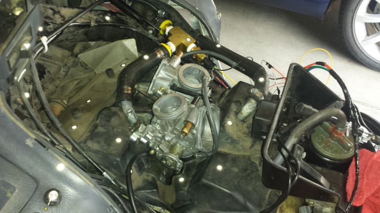
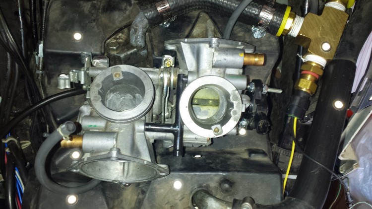
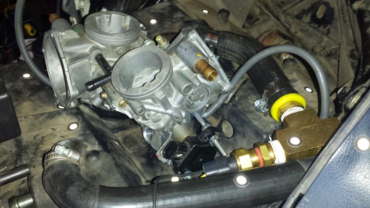
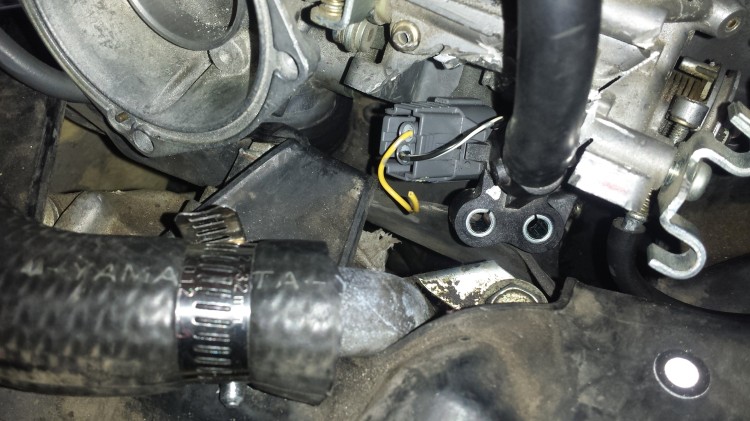
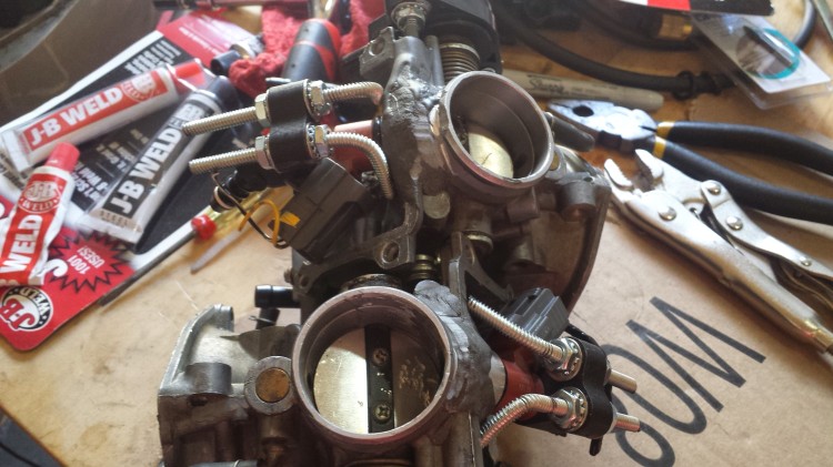
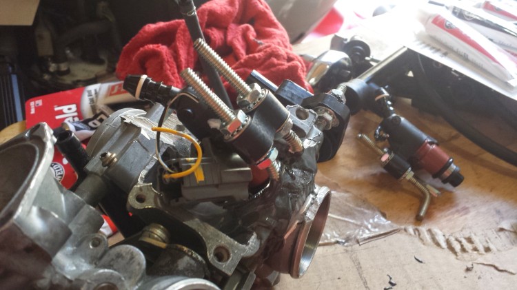
Adjusting the idle on the fuel injected PC800

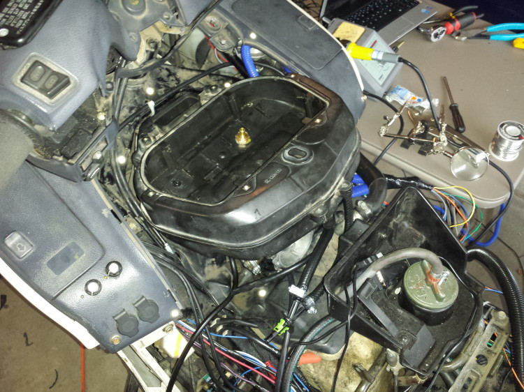
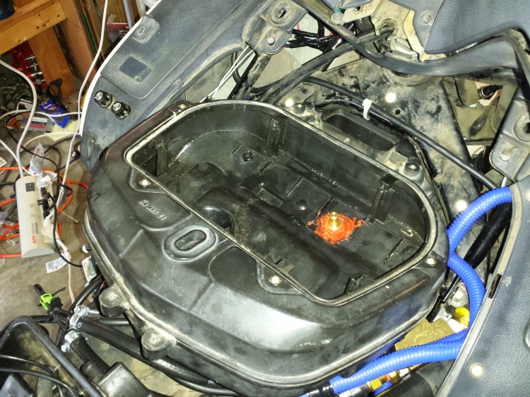
10am: After fighting with a surging idle yesterday, I re-evaluated where my MAP sensor was getting its vacuum data.  Yesterday I had changed the placement of the MAP sensor’s vacuum pickup from inside the front of the airbox near the IAT sensor to the combination of the front and rear cylinder vacuum pickups where the venturis are located below the butterfly valve plates on the throttle body.  This was giving me an incredibly fluxuating MAP reading by up to 20KPa.  Now I have moved the MAP vacuum pickup back inside the airbox and close to both intake runner trumpets.  Hopefully this will help matters and give me a monitorable vacuum source that will both change when it should based upon engine load and also not have such wild fluctuations.

I also verified that Injector 1 wiring goes to the front cylinder and Injector 2 wiring goes to the rear cylinder.  While I had the airbox off, I also confirmed that I have a good airtight seal in the throttle bodies.  Oh, and I also rewired the TPS so that it doesn’t read upside down anymore.  I had miswired the high and low sides before although that didn’t seem to make a difference to the MicroSquirt. Now I’m waiting for the RTV goop to dry in the airbox before I put it all back together and try firing up the bike again.

While I’m waiting, I’ll ruminate a bit on future spark control for the bike. Based on what I’ve deduced from the diagrams of the PC800 pulse generator wheel and the MicroSquirt V2 information (I have a MicroSquirt from circa May 2011 which means it is a V2), I believe that I can 1) get an adequate signal from the stock hall sensors and pulse generator wheel and 2) directly drive the spark generators on the bike.  One problem I might encounter is that each coil drives two spark plugs on the PC800.  The information on my MicroSquirt says that I should only be driving one coil and one spark plug per wire on the bike.  Maybe that’s a problem… maybe not.  I do know though that the spark generators on the PC800 only have two wires going to them.  One wire is +12V and the other goes to the stock ignition control module where it is grounded to charge the coil and then I believe is let float to discharge the coil.  The ignition and fuel only have a 10 amp fuse on the stock PC800 between them so I believe that the two spark generators are well below 7.5 amps each.  Once I have a stable fuel map and whatnot, I think I am going to embark on controlling spark with the MicroSquirt as well.

Noon: After much futzing around, I ended up using the Coors 16 ounce screw top beer can that I had originally planned for an oil catch from the crankcase breather hose (don’t need that anymore since I’ve gone back to the stock air box) to make a vacuum surge tank.  I tried taking MAP vacuum from the air box again but it just wasn’t working.  Now I have MAP running from the two vacuum ports on the throttle body via the beer can surge tank.  I’m getting nice, stable, and reasonable MAP readings now.
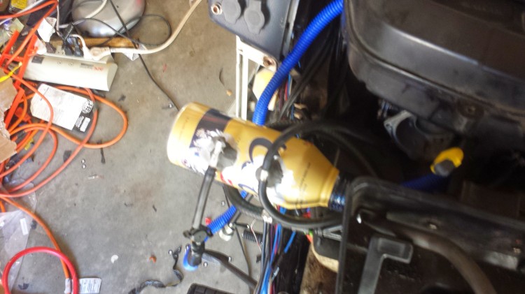
Coors 16 ounce screw top can to the rescue as a vacuum chamber to buffer vacuum from the two vacuum ports on the PC800 carbs.  Note that the can crushes in quite a bit when vacuum is pulled.  This is only a temporary solution.  In the future if this path of investigation pans out, I will experiment with reducing the volume available in the vacuum chamber until I find the lowest volume I can safely run to buffer the fluctuations from the vacuum sources.  Then I will make that chamber out of PVC pipe to resist against crushing forces of the vacuum.
Coors 16 ounce screw top can to the rescue as a vacuum chamber to buffer vacuum from the two vacuum ports on the PC800 carbs. Note that the can crushes in quite a bit when vacuum is pulled. This is only a temporary solution. In the future if this path of investigation pans out, I will experiment with reducing the volume available in the vacuum chamber until I find the lowest volume I can safely run to buffer the fluctuations from the vacuum sources. Then I will make that chamber out of PVC pipe to resist against crushing forces of the vacuum.

My next problem is saturation of the IAT sensor.  I placed it on the bottom of the air box right over the engine.  As anyone with a PC800 can tell you, the space around the air box really roasts regardless of if the cover is on or not.  I am moving the IAT to be in the ambient air stream now and take data from somewhere more in line with the actual temperature of the air the engine is receiving.
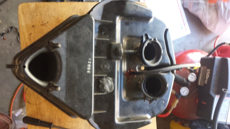
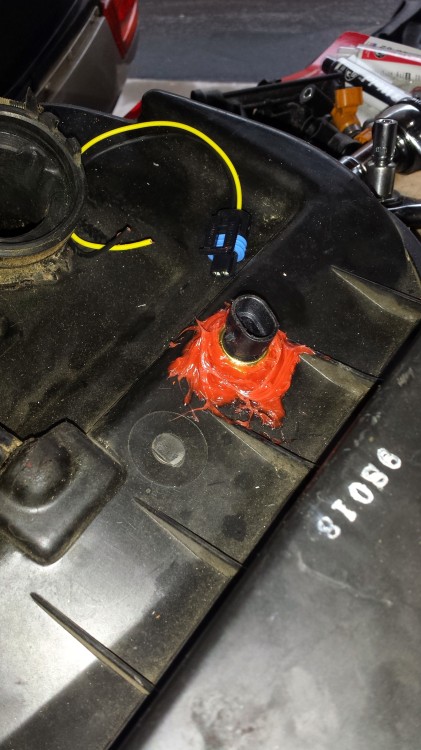
Plugged up hole where the IAT sensor used to be located in the air box.

1pm: I moved the sensor to be in free air and now I am getting realistic readings from that.  However, that didn’t fix my idle problem.  I’m still getting either very high idle (~3500RPM) or very lean AFR (~16-17).  I then decided to remove the air box to see what happens.  Lo and behold, the problem is exactly the same.  Next, I tried closing up the air intake stream using some plastic lids.  The more I closed the stream, the more the idle came down and the more the AFR started correcting itself until I got to the point where I had 1100 RPM and 13.5 AFR which is pretty good considering the VE table I’m using is absolute garbage and a complete guess on my part.
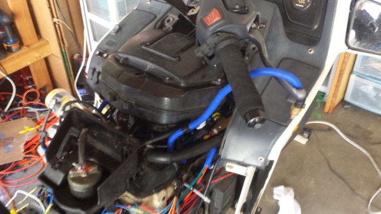
A blurry picture of the IAT sensor hanging off the clutch lever in the free air.

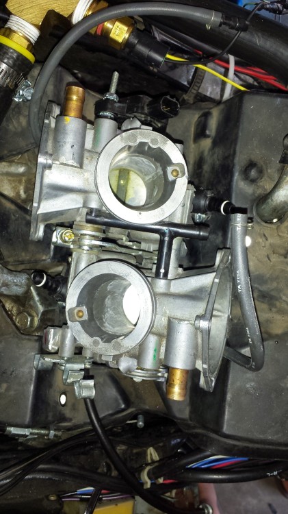
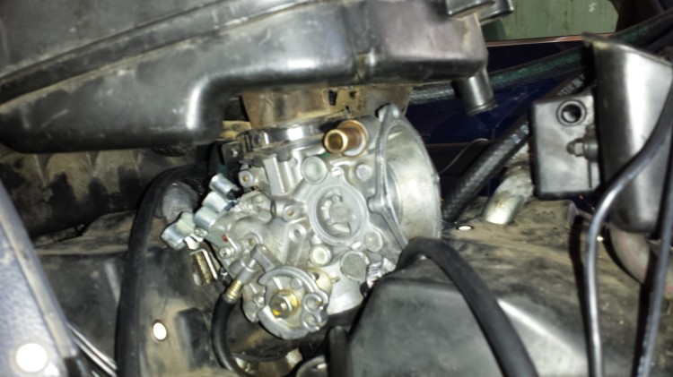
I think this means that the PC800 carbs when turned into throttle bodies let too much air through.  I’ve gone back through and checked for leaks everywhere but there are none.  Everything is sealed as it should be.  The cross sectional area of the PC800 carbs where air can go through (ignoring the butterfly valves) is about 2.66 square inches across both cylinders.  I calculated that number as follows:

pi * (diameter of one cylinder intake / 2)^2 = area of one cylinder intake

area of one cylinder intake * 2 = area of all intakes

sqrt(area of all intakes ÷ pi) * 2 = diameter of all intakes

And for the PC800, this is:

pi * (1.3 inches / 2)^2 = 1.327 square inches

1.327 square inches * 2 = 2.66 square inches

sqrt(2.66 square inches ÷ pi) * 2 = 1.84 inches for the diameter of all intakes

For comparison, on the VT1300CXA, the area of the throttle body is only 1.65 square inches (the diameter is 1.45 inches for those who want to do the math).  Looking at the butterfly valves on the PC800 carbs versus the VT1300CXA throttle body, it appears the VT1300CXA seals a little more than the PC800 does as well.  Is that enough to really make a difference?  I don’t know but I’m guessing it might be…

At this point, I’m trying to decide what I could do to rectify this problem, if it really is a problem.  I could try to hack together a way for the VT1300CXA throttle body (not the intake runners and injectors) to mate with the PC800 throttle body and remove the butterfly valves from the PC800.  I could try to put in some sort of restriction on the air intake for the PC800 although that would probably starve the engine for air at high loads and high RPMs.

2pm: During lunch I thought about my problem more deeply.  In looking through the excellent Performance Fuel Injection Systems book written by the guys at DIY Auto Tune, I found some information in the fuel delivery section of the book (page 21 in the first edition) on how to calculate a proper throttle body size.  The formula for the cubic feet per minute is:

(maximum RPM * VE * engine displacement in cubic inches) ÷ 3456 = cubic feet per minute

I don’t know what volumetric efficiency will be on the PC800 but I’m going to guess it’s about 85%.  The engine displacement for the PC800 is 800cc or 48.8 cubic inches.

On the PC800, the formula looks like:

(7500 * .85 * 48.8) ÷ 3456 = 90 CFM

Next, the Performance Fuel Injection Systems book tells me to convert the cubic feet per minute calculation I just did into a maximum throttle body area with the following formula:

(CFM * 2.4) ÷ 300 feet per second = maximum area of throttle body (square inches)

For the PC800, that formula is:

(90 * 2.4) ÷ 300 = 0.72 square inches

Converting this into a diameter using this formula:

2 * sqrt(Area ÷ pi) = diameter

Using that formula, we get a total effective diameter of:

2 * (sqrt(0.72 ÷ pi) = 0.957 inches

That is much different than the 1.84 inch effective diameter of all intakes for the PC800 throttle body that I produced from the PC800 carbs.  I double-checked all of this with the simple calculations that can be done on this page and came back with 1.2 inch effective diameter.  Close enough, especially since these formulas are most likely all empirically derived rather than based on any sort of fundamental theory.

I suspect that the slides in the PC800 carbs block a large amount of airflow at low RPM and open up more at high RPM based upon the vacuum bellows that they attach to.  In effect, the slides are almost like a RPM-actuated damper valve found on some of the higher end V-twin muscle bikes put out by Honda and Yamaha.  Interesting!

For the PC800 carbs to work as a throttle body, I would need to reduce the overall intake diameter to just under 1 inch.  I believe that my options are either to block part of the flow at the top of the PC800 carbs-turned-into-throttle-bodies or block the flow at the air box intake.  The air box intake will be a bit tricky as it is a triangular shape rather than a circle or square.  However, if I can reduce the area out at the end of the air box, then I could pipe in the IACV into the air box.  Otherwise I might have to drill new holes in the PC800 carbs below the butterfly valves in order to pipe in IACV air.

2:30pm: I did a test where I took off the top-most piece of the air box that is removable (rectangular-looking thing) and blocked air flow with my hand.  By blocking air flow there, I was able to change the speed of the engine and the AFR as well, even with my bad VE table.  I’m pretty sure this means that I need to constrict the amount of airflow that the throttle bodies receive.  One potential problem I observed with restricting airflow where I did is that the air box actually started to collapse in on itself a little bit due to the vacuum that started building.  That isn’t particularly desirable!
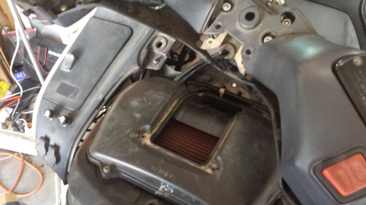
The rectangular opening where you can see the K&N air filter through is what I was using to adjust how much air was coming into the air box.

What I might try doing is getting some relatively thick tin or sheet metal and cutting it into circles that could slip in above the PC800 carbs/throttle bodies and below the air box connector.  I would drill holes in the sheet metal of the correct diameter to allow the proper amount of air through.  That just might work.

Now it’s time to go down to the river for some afternoon summer tubing.  I’ll come back to this project hopefully later tonight.  I’m pretty sure I have some sheet metal sitting around my garage somewhere…

Trouble with RPM sensing

11am: I’m having some trouble with RPM sensing on my MicroSquirt. Previously I thought that I had fixed the problem but it appears to be back. The bike is otherwise in good health.  I would consider taking my RPM data directly from the ignition pulse triggers but the pulse generator plate (shown as #22 here although I haven’t been able to find a part number for it in the microfiche yet.) has an oddly configured set of teeth.  There appears to be difference in the spacing and also the thickness of the ring.  This page and this page in the shop manual show that the bike actually has dual triggers for spark. The second figure on the second page linked in the last sentence shows what I think indicates that the bike’s ignition control module determines when to fire a spark based upon the absence of material rather than actually counting teeth.  I however don’t know if this is true or not.  Unfortunately I don’t have a man on the inside at Mother Honda in Japan to tell me the secrets that I need to know.

1pm: It looks like I’ve solved the RPM sensing problem.  I discovered that I had the wires reversed for the RPM sense circuit.  There is a small note for Pins 30 and 31 here that indicates the OPTION + should be connected to the ground terminal on my bike and the OPTION – should go to a clean 12V source.  This is a bit backwards compared to what I’d expect but it seems to work.  Now I am reading 800-900 RPM pretty consistently when cranking at the starter.

2pm: LIFE!  I just had the bike up and idling!!!

3pm: Tuning is starting in earnest now.  I’m having some troubles with a few quirks in the TunerStudio software.  Also it appears that the shorter I set the pulse for the injectors, the more fuel is actually delivered.  Not sure what that’s about!  Also I can’t get the air fuel ratio up high enough even at hot idle.  At hot idle, it’s ranging around 10.3-10.5 when it should be more like 14.7-15.2.  I can’t figure out what to adjust to lean out the mixture but without reducing the idle speed.


I am looking for help on the MicroSquirt forums now for some of my questions.  Hopefully I’ll have more time tomorrow to work on this.

Finishing the PC800 Fuel Injection Throttle Body, Wiring, Air Box, and First Start

20140708_153058The last time I posted an updated on my Honda Pacific Coast fuel injection project, I was moving ahead with using a VT1300C throttle body.  I had started to make 3D cad files to have a metal adapter 3D metal printed to fit everything together.  Alas, I discovered that the VT1300C throttle body will not work on the PC800 due to the geometry of the PC800 engine and the VT1300C throttle body.  There just isn’t any manageable way to make an intake runner to couple the throttle body and the engine together.  The picture above shows a mockup with some moulded rubber hose.  Yeah… not going to work.

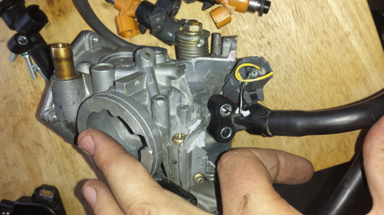
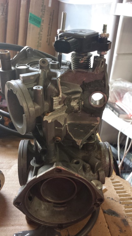
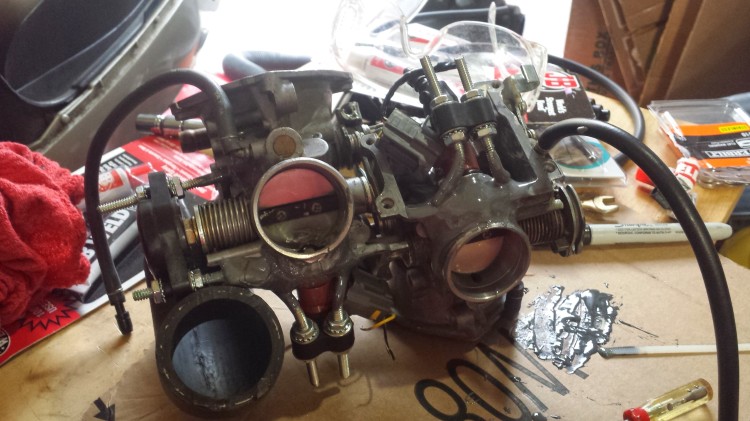
20140708_153944Thus I moved back to using the PC800 carb that I had started modding several years ago.

20140708_164032

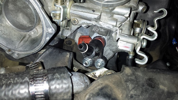
I pulled off the fuel injectors and fuel injector retention clips from the VT1300C throttle body to use on the PC800 carb-converted-to-throttle-body.  Turns out that they work pretty well together.  Note that this isn’t the end orientation of the retention clips.
20140713_152012

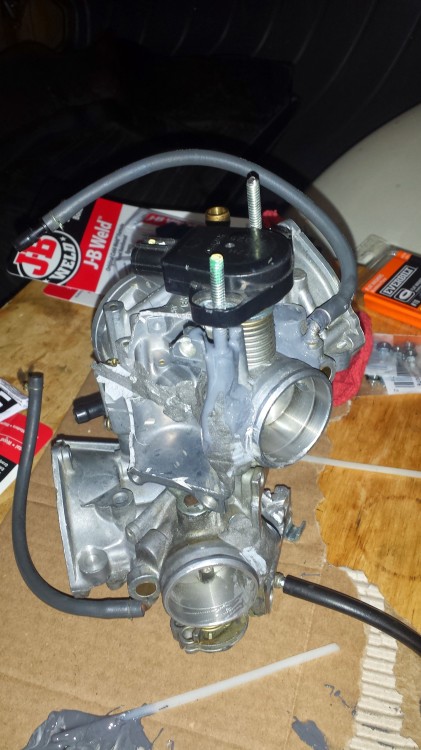
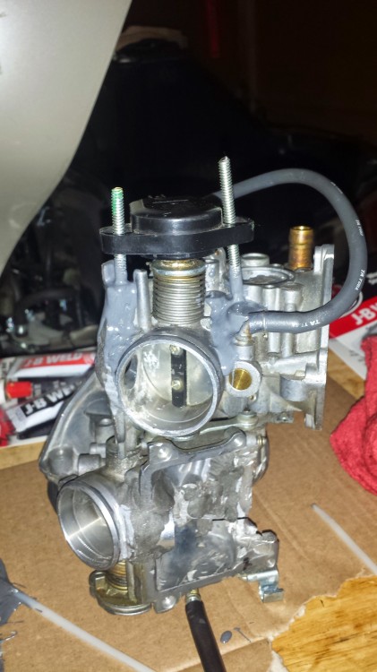
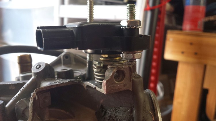
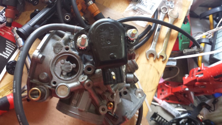
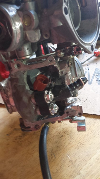
I then worked on installing a throttle position sensor off of a set of CBR600RR throttle bodies I had purchased some time back as part of this project.  I used some allthread and JB Weld to make a mounting point on the right hand side of the carbs.  The bolt that runs through the carbs from the throttle cable wheel to the spring on the other side works well for turning the potentiometer inside the TPS.
20140713_152020

Another view of the gloppy mess of JB Weld.

20140716_160918

I used some washers and nuts to hold everything together.

20140716_160928

I also had to make some plastic spacers due to size issues with the nuts.

20140716_160954I’m a bit surprised that it worked as well as it did.

20140716_161051

No issues with clearance.

20140716_161057

It tucks in nicely next to everything.

20140716_161127
20140725_093657Next I worked on placement of the injectors and their associated parts.  Surprisingly, I found that I didn’t need to cut any additional material from the old PC800 carbs to fit the injectors and their retainers into the top of the engine area.

20140725_093707

Looks good here, too!

20140725_095138

More test fitting.

20140725_101527I cut up some allthread to make retaining the injectors and the high pressure fuel lines a possibility.

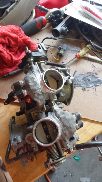
20140725_103014Then I bent the allthread so that I could use some JB Weld to hold the allthread to the PC800 carbs.

20140725_104350

Both sides bent up and ready for JB Weld.

20140725_105107

Putting a layer of JB Weld on.

20140725_145314

It got pretty goopy using normal JB Weld.

20140729_104004The next day I used some JB Weld in the stick form like I had originally used on the injector bungs to finish the job and make everything very secure.  I ended up going with the normal stick rather than the high temp stick.  Hopefully that doesn’t give me problems later.
20140729_104016

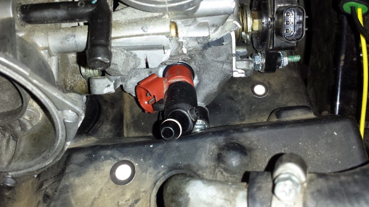
Closeup of one injector mounted in place.  I trimmed the allthread short so that everything fits into the space above the engine without interference.
20140729_104131

Test fit in the engine.  Everything looks good.


20140729_104158

Plenty of clearance.

20140729_104207

Good on this side, too.

20140729_111637Next I worked on getting the fuel lines plumbed in to clear the stock air box.

20140729_111646

Everything looks good here, too.

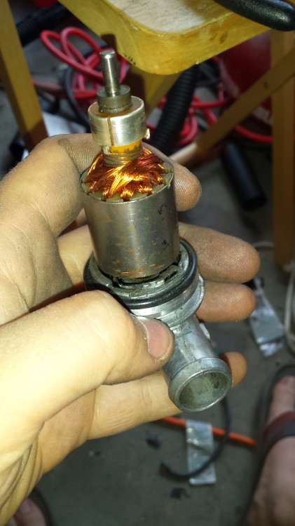
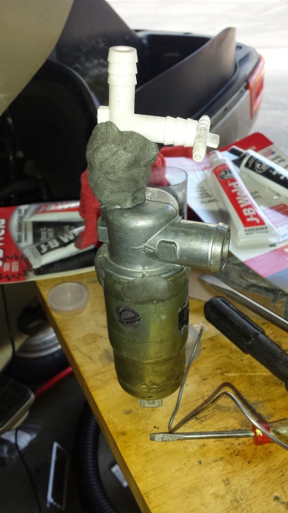
20140729_114448Then I took some time away from the carbs/throttle body to modify a Bosch idle air control valve to work as the IAC for this project.  The spring was old and tired so I had to open the unit up to modify things internally.  I ended up moving the retainer for the spring about 1/8th of a turn and using some JB Weld to hold everything in place.  This is a Bosch 0 280 140 505.  I bought mine on EBay for a few bucks compared to quite a bit more as a new part.
20140729_120039I still need to get a vacuum cap for the top large barb and a three wire plug for the bottom to interface with the MicroSquirt.  That will probably happen this afternoon.  Wiring is straight forward for the three pin Bosch units.
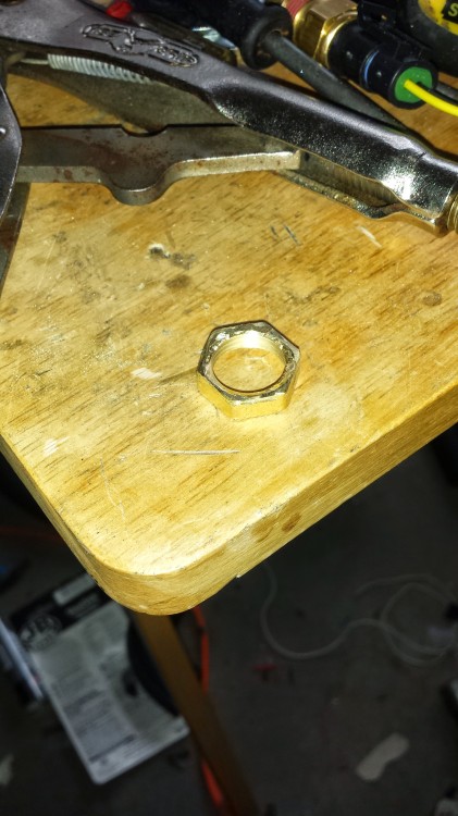
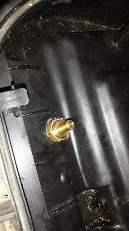
20140729_191205Next up, I modified a brass water pipe fitting to work with the temperature sensor that I installed in the PC800 air box to work as the intake air temperature sensor.

20140729_191621Here’s the IAT installed in the air box.

20140729_191626Another view before I gooped it with RTV sealant.

20140729_192236Sealant on the bottom.

2014-07-30Here it is as a test fit.

20140730_104839I then worked on installing the wiring in the bike in a clean way around the throttle body.  I used some convolute tubing to tidy everything up.

IMG_20140730_112133Then I mounted the air box onto the carbs and connected everything up.

Then this happened! 😀

Yes, the bike ran (just a little) on my first try starting it up with fuel injection.  I have no fuel leaks (so far) and I have the start of an idle tune.  There are still some things to do to the bike before I can button everything up and tune beyond idle.  I discovered today that I misplaced the breather tube that connects the head cover outlet on the rear cylinder to the air box.  The Honda part number is P/N 17225-MR5-000 and it is no longer made or available.  Luckily I found one on EBay that should be here within five days.  I also still need to install the Bosch IAC valve on the bike although that doesn’t have to happen right away.  Both the vacuum lines that will connect to the IAC and the air box barb that will connect to the breather tube have their holes currently plugged so it will not impact initial tuning.

Were it not for being such a rainy day, I would be down in the garage working on the tune.  However, I don’t want to risk burning up everything in the garage since I can’t put stuff outside due to the wetness falling from the sky.  My next real chance will be on Friday.  Maybe then I’ll start getting a decent tune put together and be able to button up the wiring.