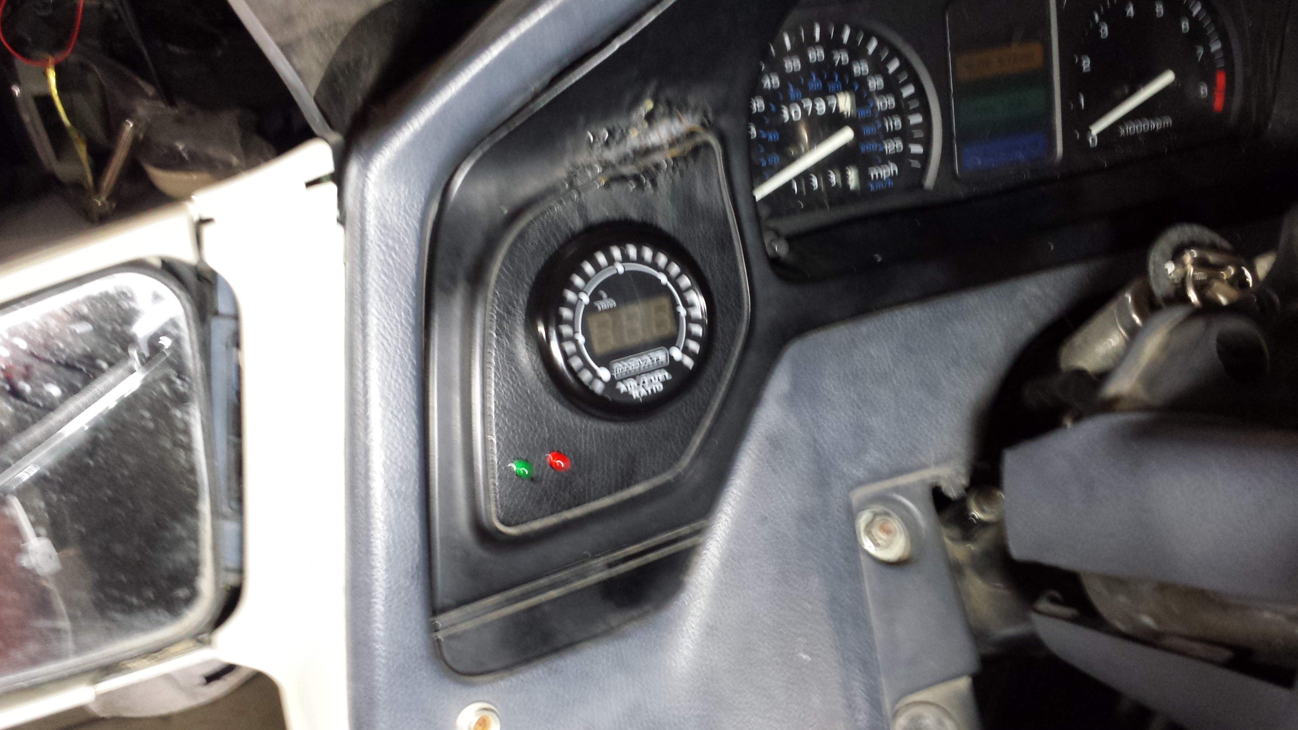
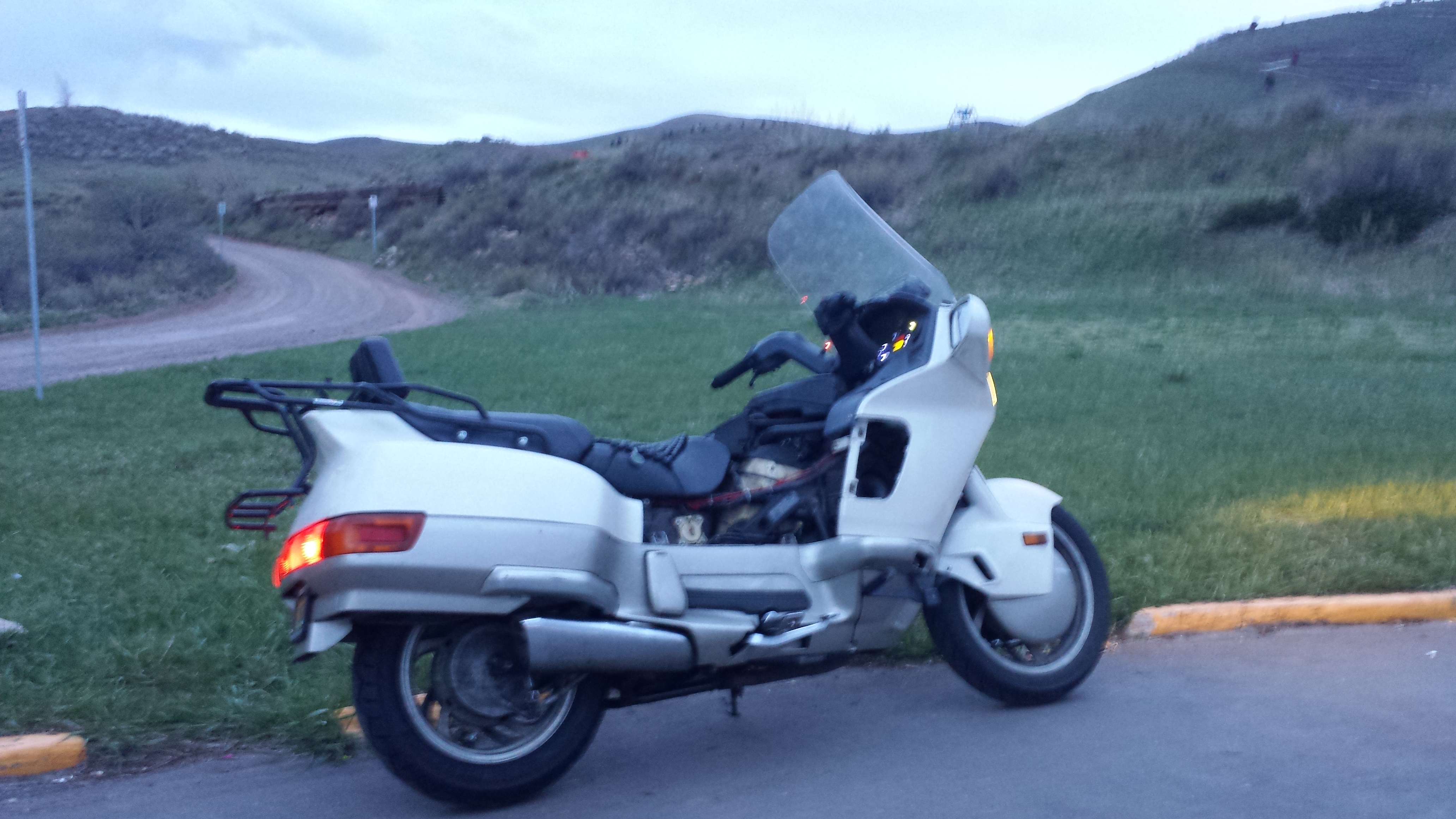
Progress continues on the Honda Pacific Coast PC800 fuel injection conversion. Over the last week I installed the Innovative Motorsports Wideband O2 sensor and gauge on my bike. The gauge fits perfectly into the left speaker blank spot. The red and green LEDs below and to the left of the gauge are wired into the warm-up and accel enrichment indicator wires on the MicroSquirt. I might add another LED in there later as an “idiot light” for diagnosing if the bike doesn’t start due to power loss to the MicroSquirt or fuel pump from having the stop/run switch that is located on the right side of the handlebars in the wrong position.
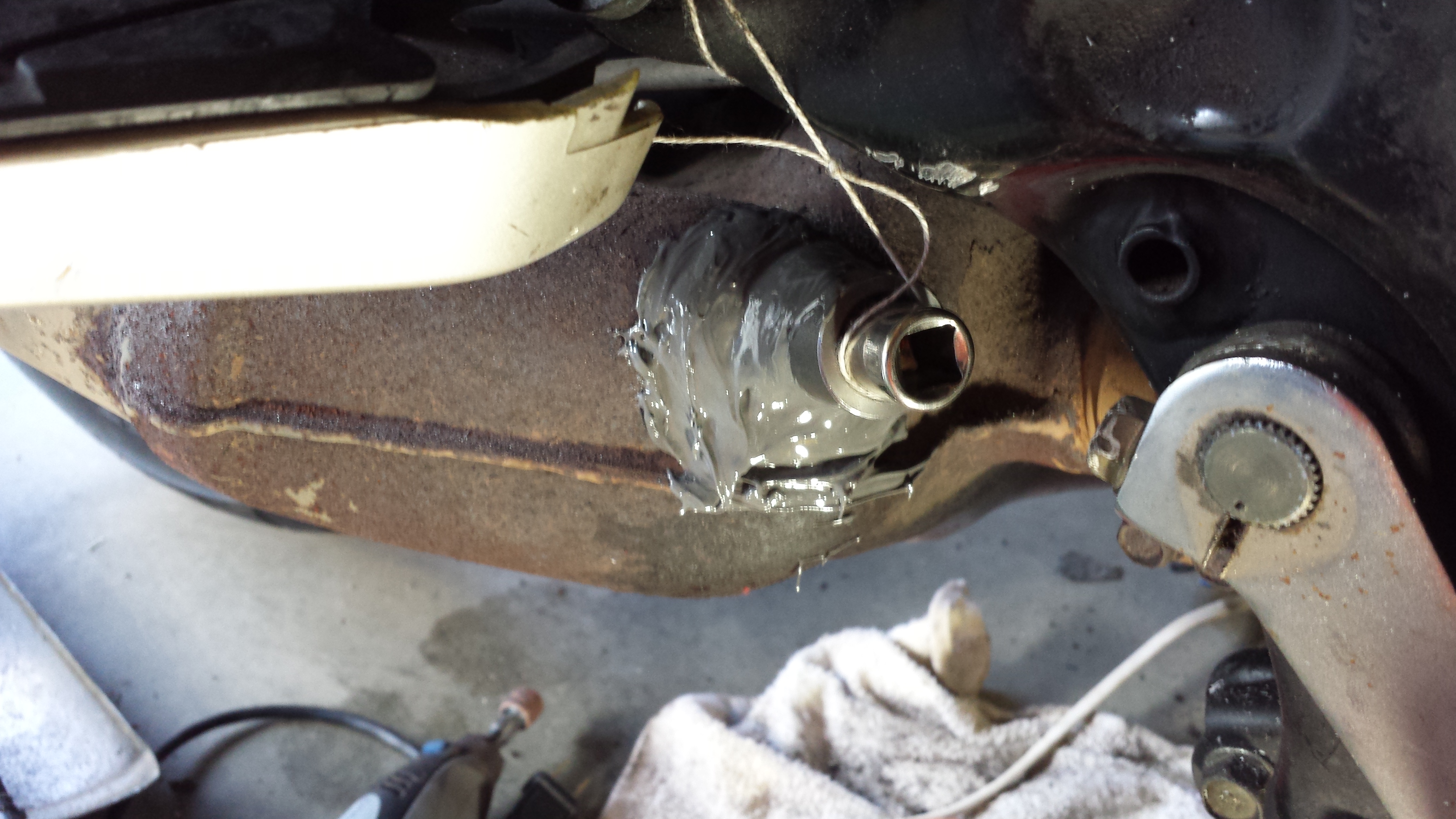
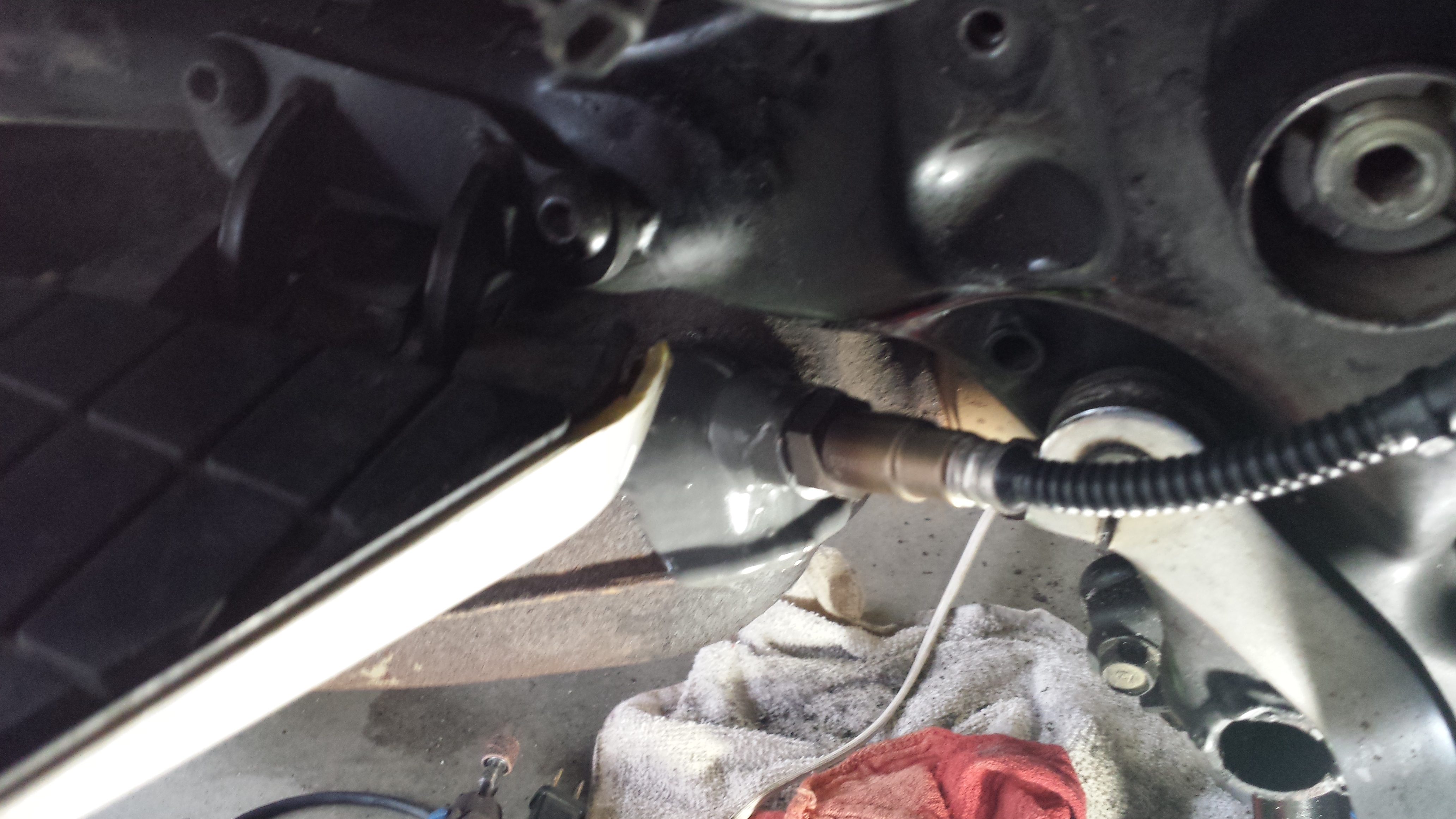
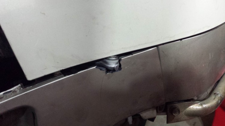
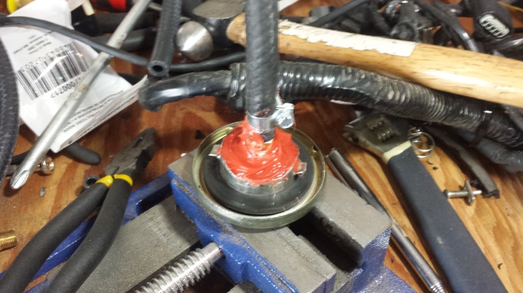
This is the exhaust collector just before it morphs into the muffler. I used a dremel and a hand power drill to carve a hole into the metal where I then placed the wideband O2 sensor bung. I used JB Weld (after sufficiently cleaning the metal surface of rust) to hold it in place rather than using an actual welder. I don’t own a welder (YET) but the JB Weld should hold just fine in this application. The bung was held in place with a socket extender wrapped in electrical tape and some string tied around the rear passenger footrest. It took a little work to pry the socket extender out after the JB Weld had cured but I was able to do it.
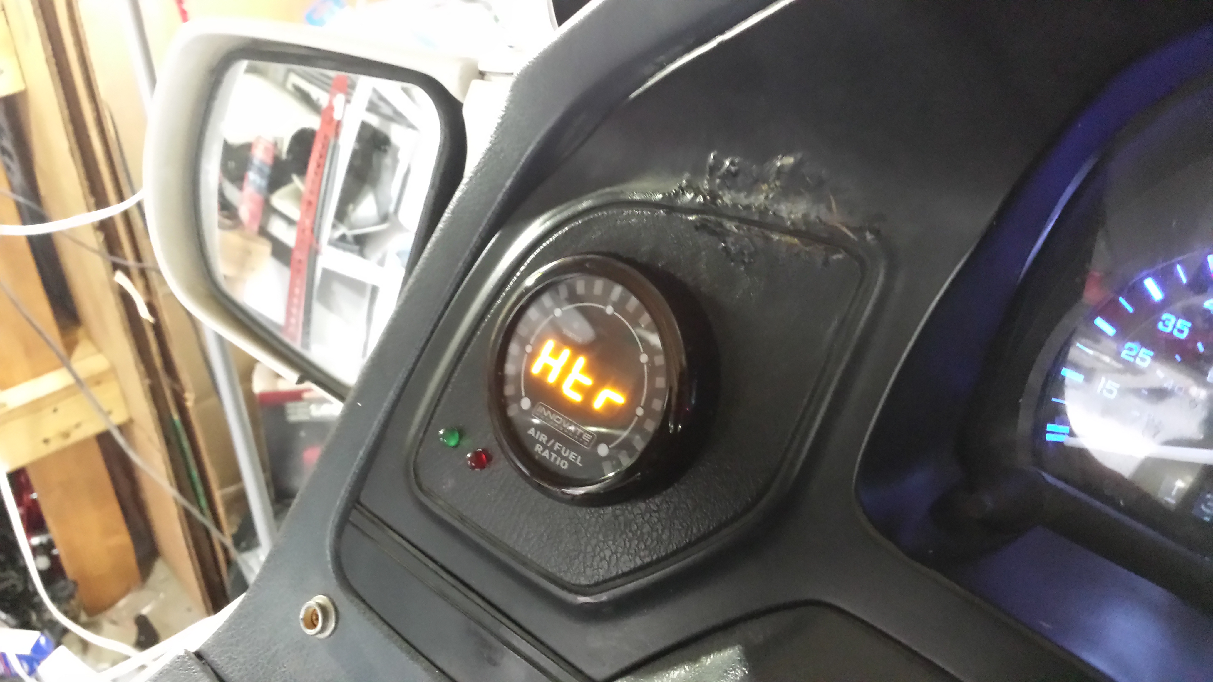
Turning on the Innovative Motorsports gauge for the second time. I previously had turned it on without the sensor attached in order to start the calibration process. Now the gauge is turned on with the sensor attached but out in the open air to run the calibration routine.
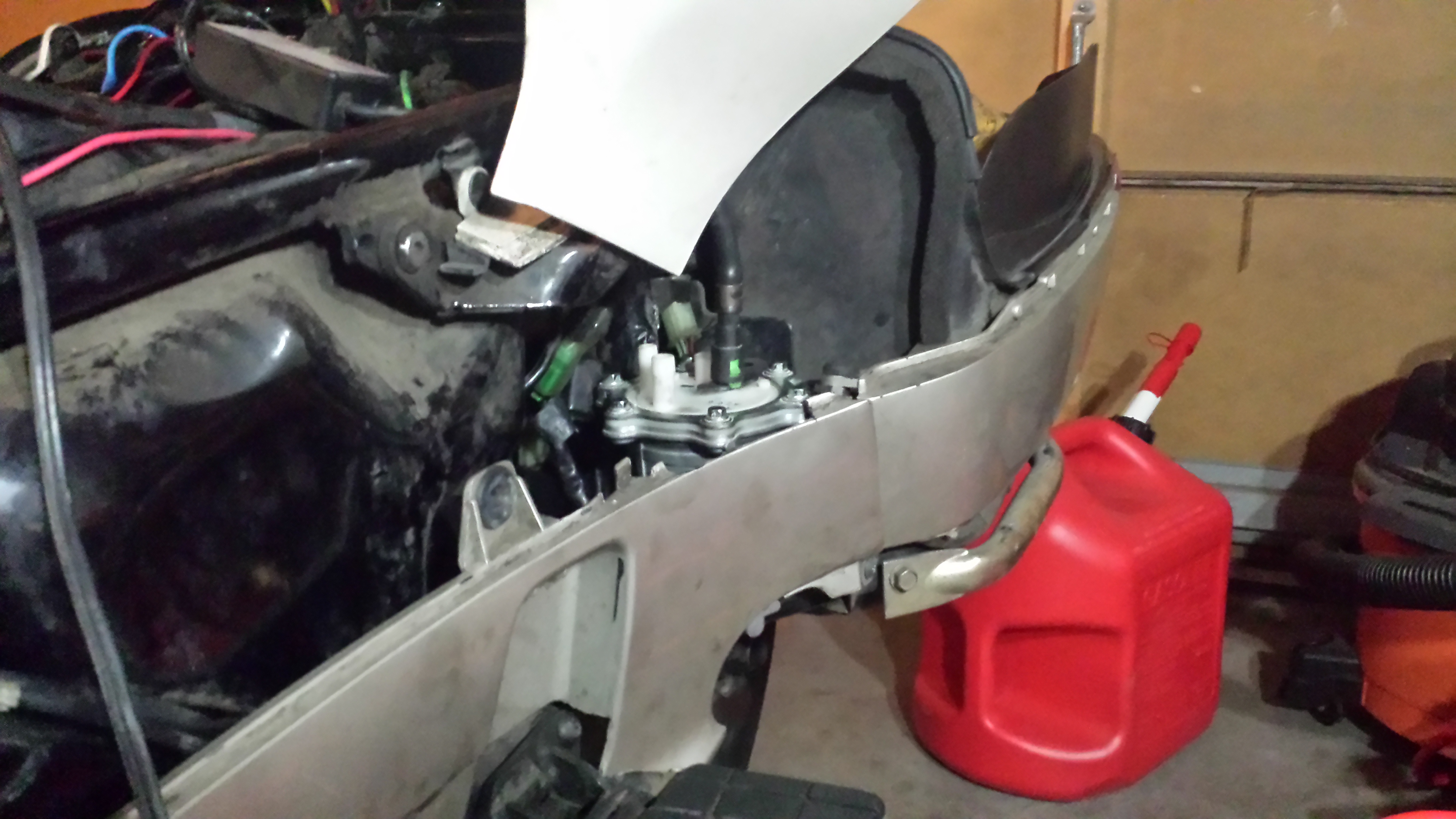
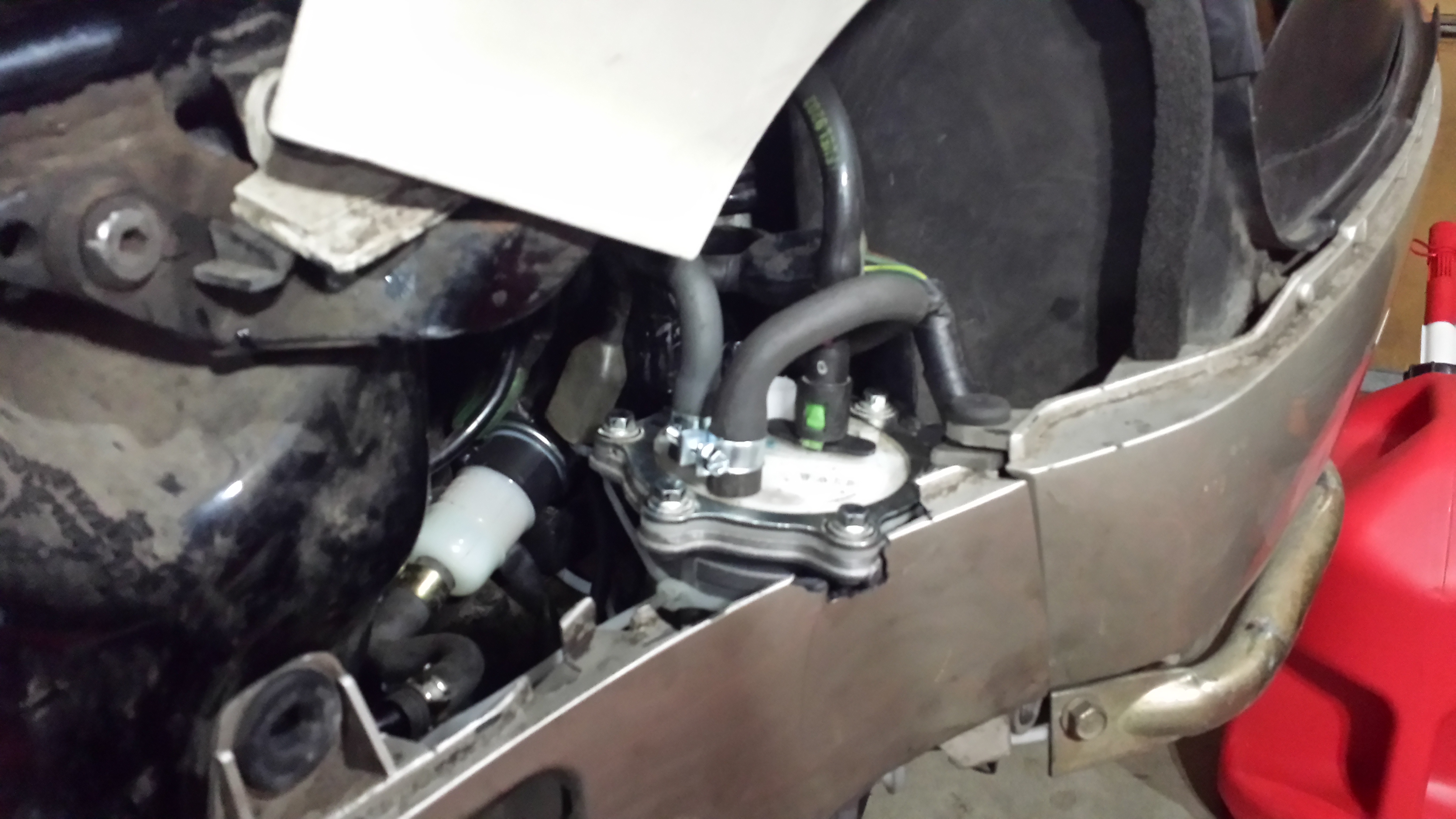
Here is the sensor installed. It should fit snugly behind the plastics. Routing the sensor harness was a bit challenging. I ended up running it over the front tube frame members and down the right side of the bike. I put the huge sensor connector on top of the battery which also helped take up some of the excess cable.
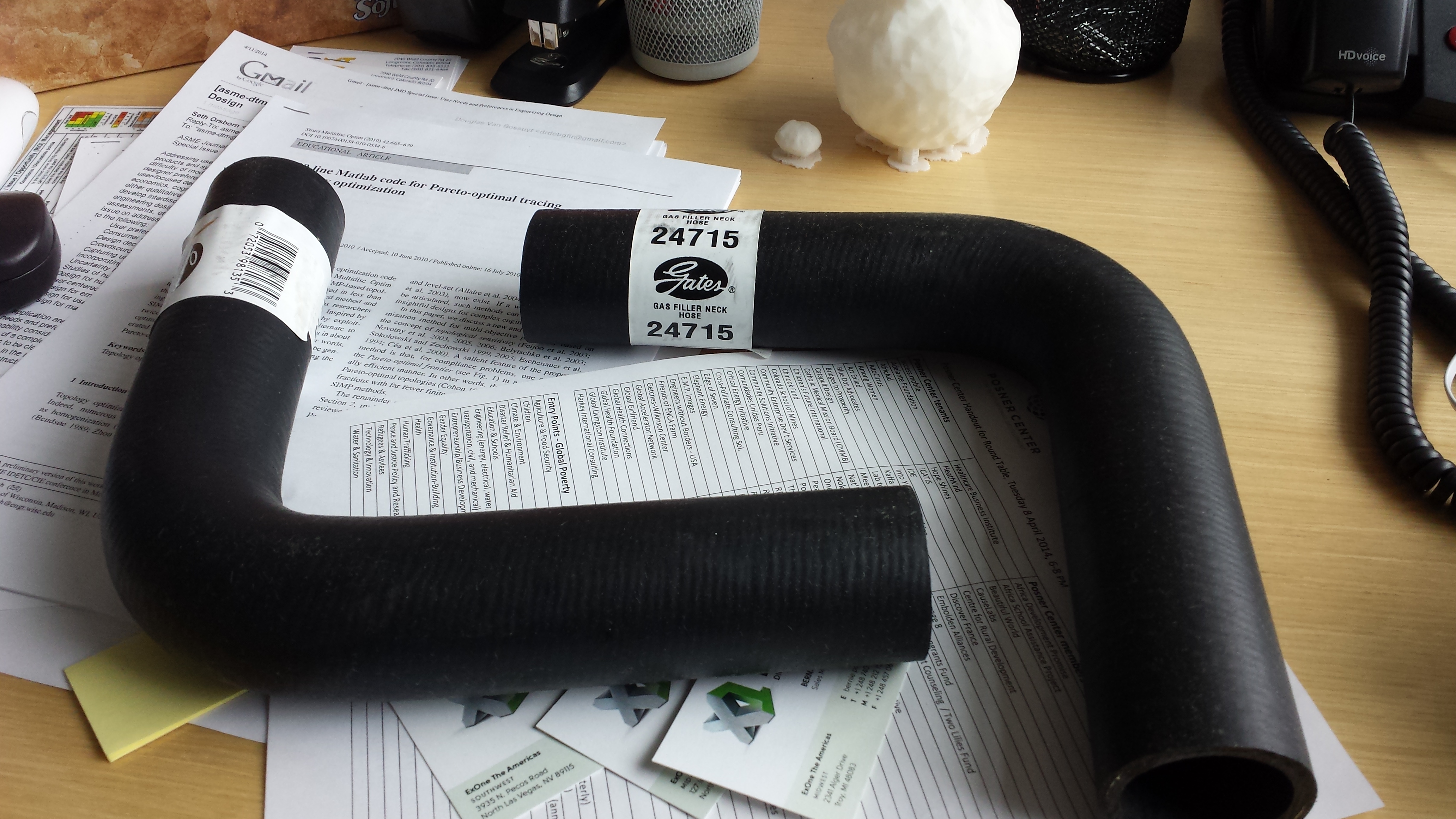
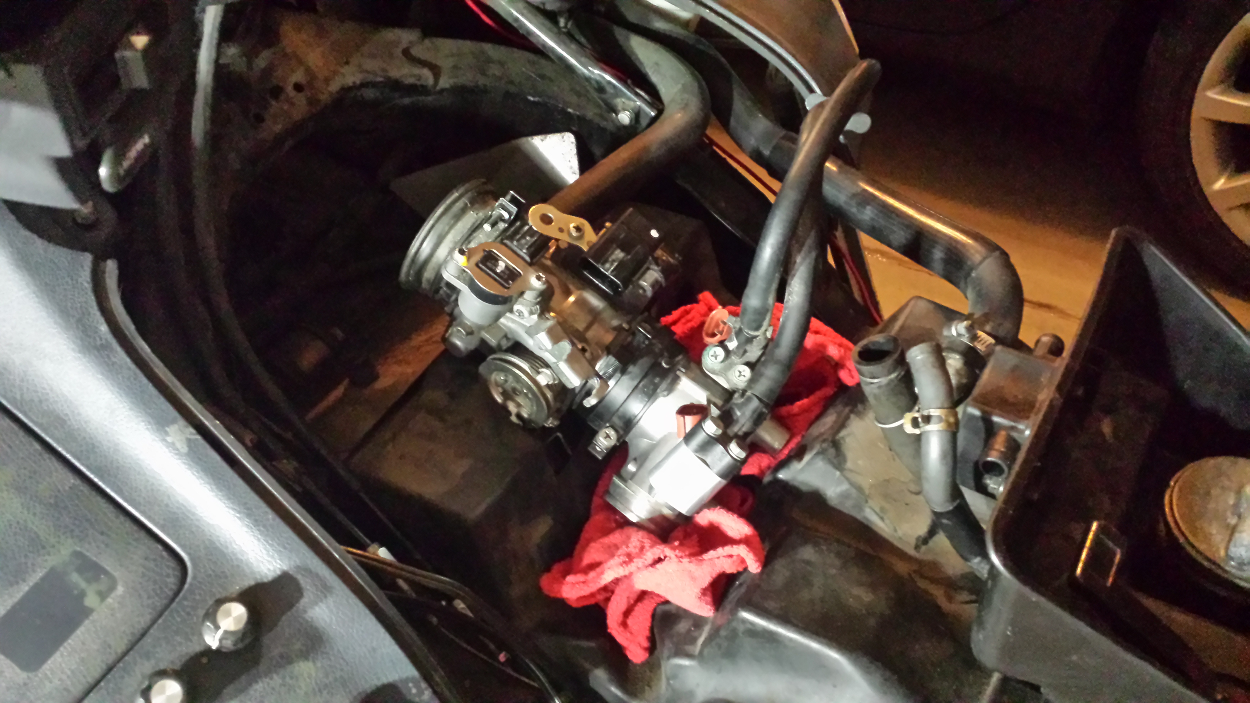
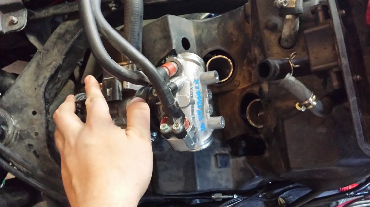
Now for a few other odds and ends. These are going to be the intake manifold boots. They are fuel filler hoses that I bought on Amazon. They are 1.5″ ID which is just a little smaller than both the throttle body off the VT1300CX Honda Fury that I am using and the PC800’s engine intakes. They will both be shortened and fixed on the appropriate places. I am thinking that this probably isn’t a permanent solution and am already looking into having a 3D printed metal coupler made to connect between the PC800 carb boot insulators and a similar set on the Honda Fury intake.

This is the idle air control valve off of the Honda Fury throttle body. It is a stepper motor. The MicroSquirt ECU doesn’t have provisions for controlling a stepper motor like its bigger brother, the MegaSquirt III. It is technically possible to add the circuitry although my soldering skills aren’t up to par in order to solder on very fine-pitch surface mount IC pins.
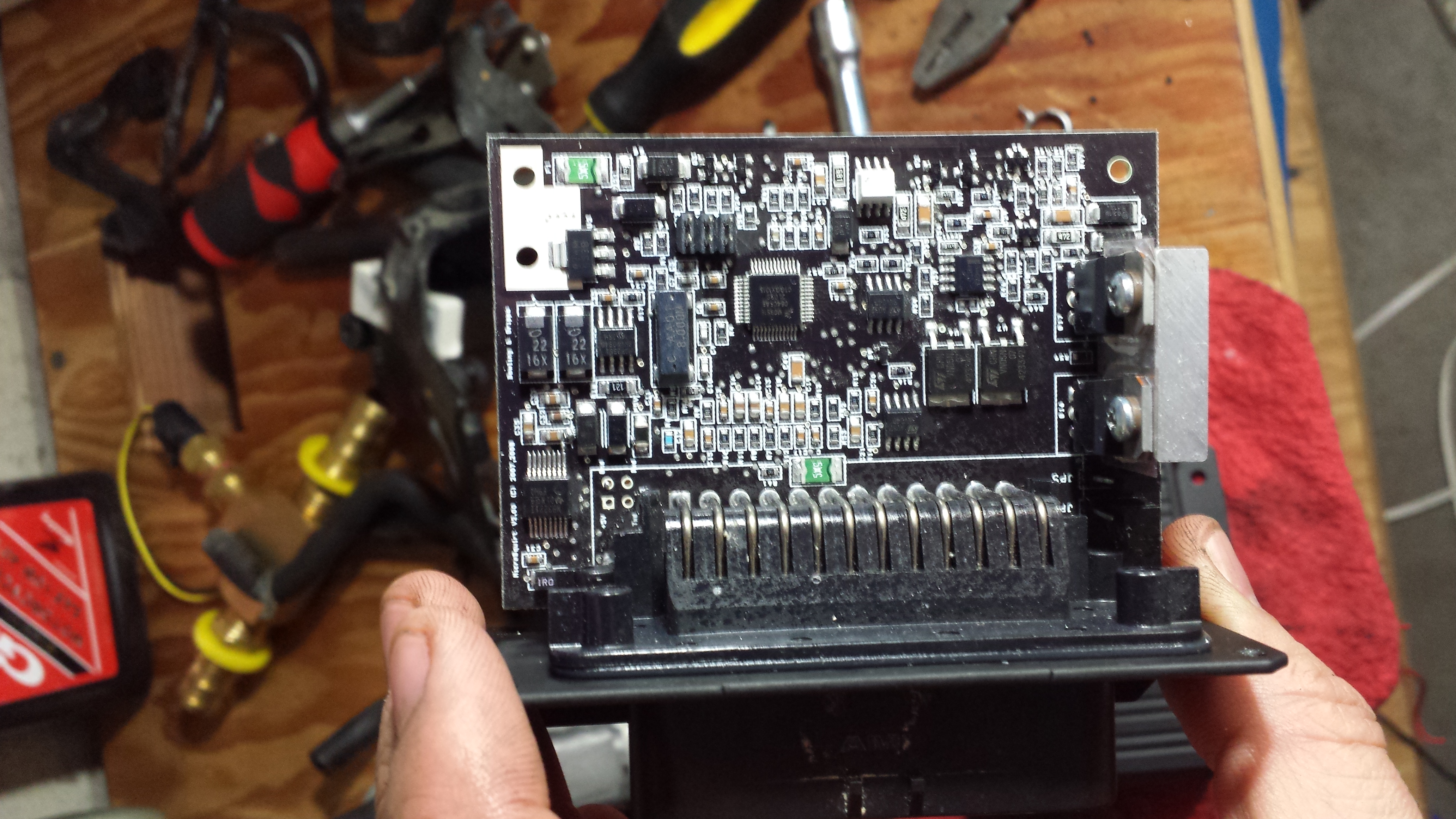
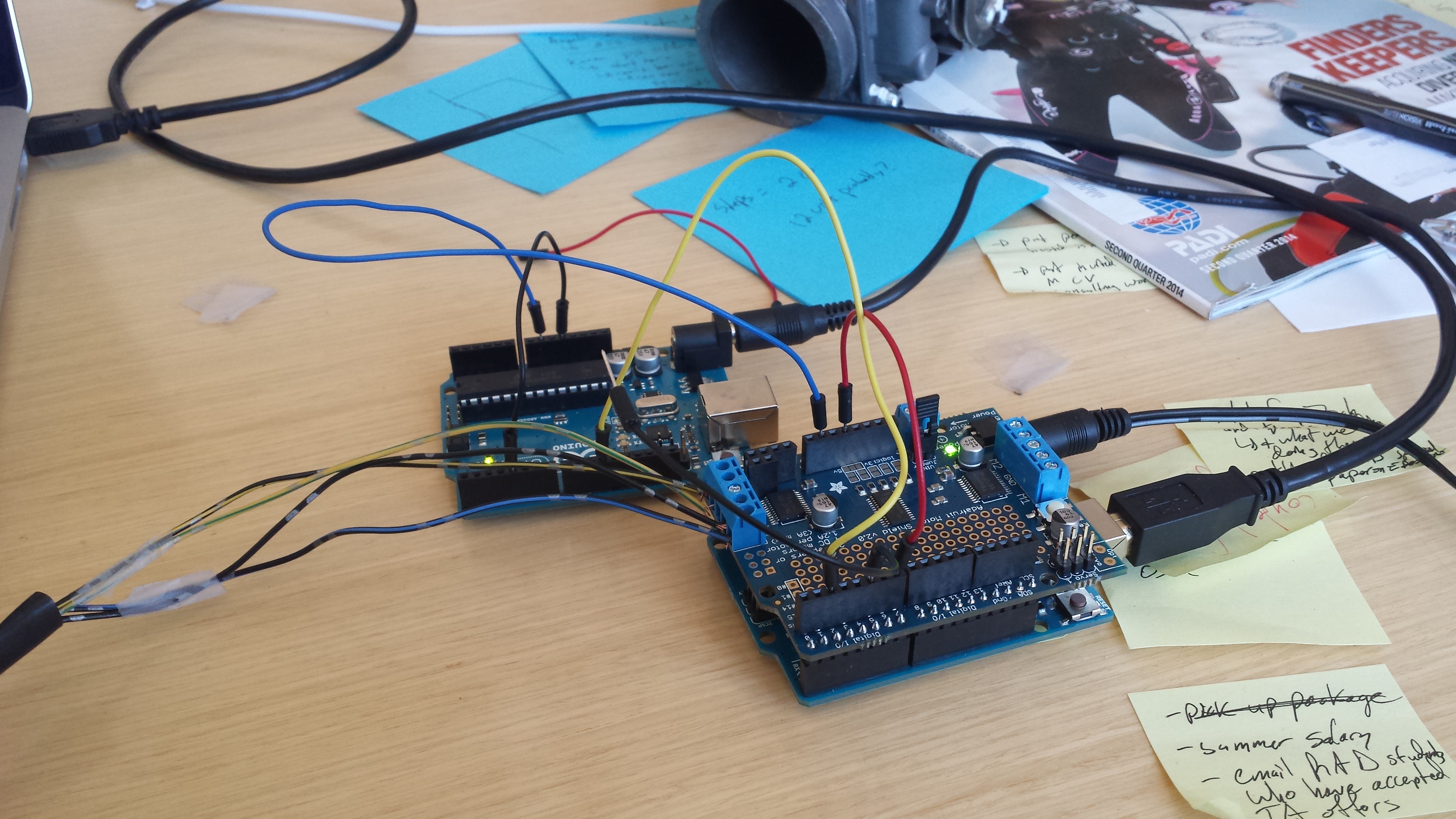 I was playing around with some Arduino boards to decode a PWM signal from the MicroSquirt (the MicroSquirt can do PWM and solenoid control for idle air control valves) and then run the stepper motor. Rather than deal with the headache of building appropriate circuitry to protect the Arduino from all of the noise on the 12VDC lines on the bike, I finally decided to buy a used idle air control valve that uses PWM from eBay. It took me a very long time to find one that I am sure is a PWM valve and that only has two wires (meaning it has a spring return). More to come on that in another week once the parts come in!


