Today I powered up the MicroSquirt for the first time on my Honda Pacific Coast PC800 fuel injection project. I bought the MicroSquirt several years ago but life got in the way and only recently have I been able to get serious about the project again.
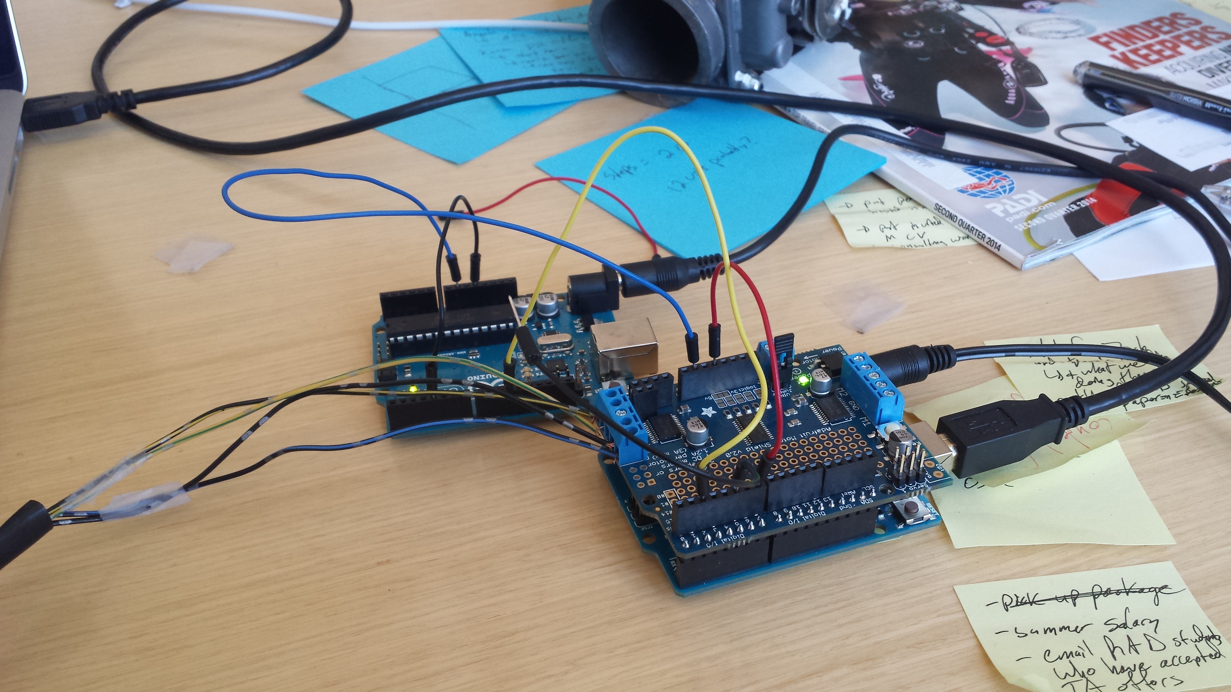
The main contributions to the project I did today surrounded verifying that wiring is correctly installed and calibrating sensors. This is also my first time using the TunerStudio MS software. I am still debating if I will purchase the advanced functionality or stick with the standard free version.
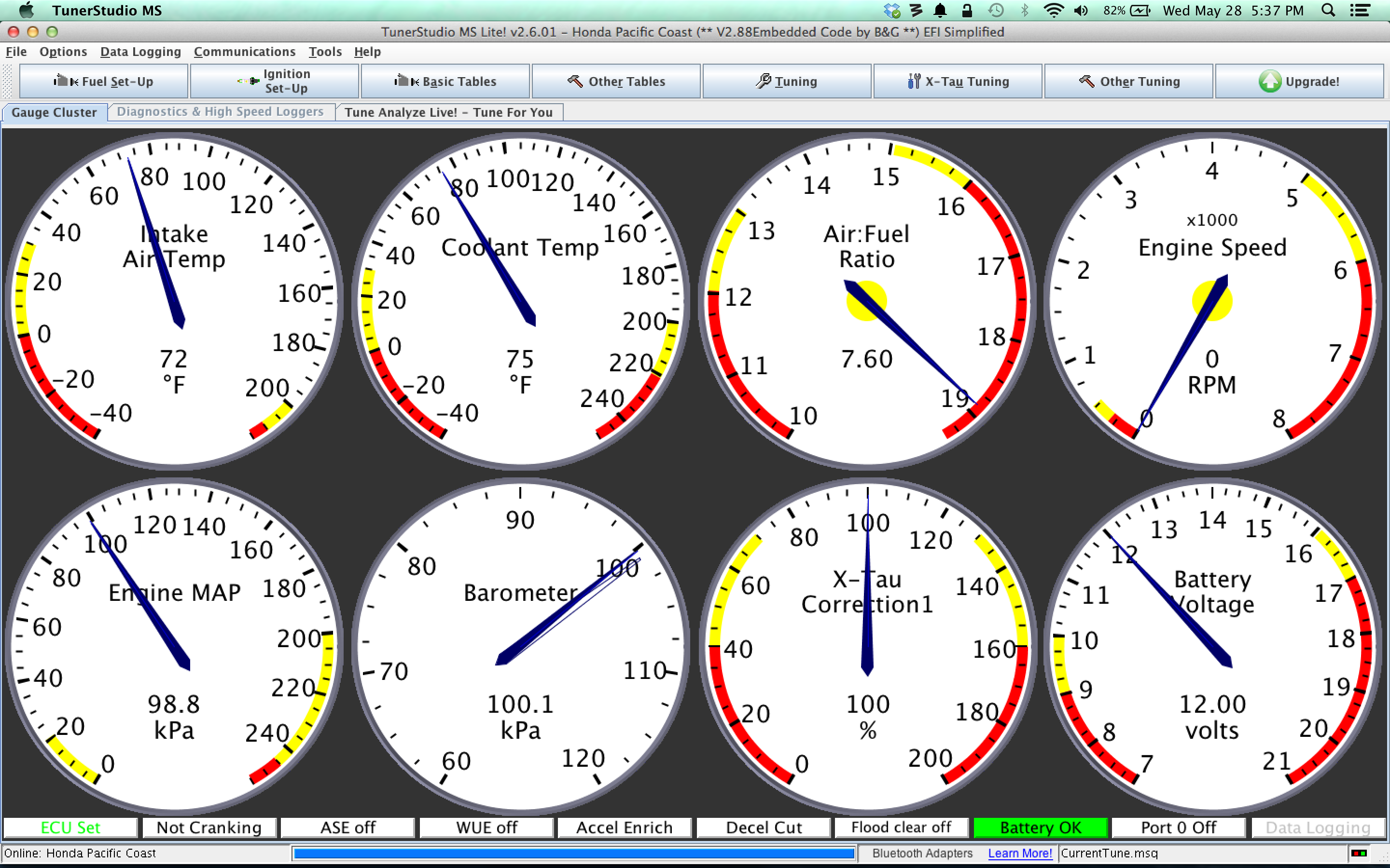
Here is a screen capture of the TunerStudio MS software running with the MicroSquirt. I did not enable the fuel pump today so what you see here is simply a static test. I did try some cranking though to verify that RPM sensing from the negative terminal on one of the spark generators was working correctly. After initially having a bunch of noise problems, I found this post on a forum dedicated to the MicroSquirt. It led me to add a diode and 1K ohm resistor in parallel on the RPM sensing wire. I also moved the wire to a slightly different position to avoid any noisy AC signals from the stator or the other spark generator wiring. That seemed to solve the problem. Also, it will provide protection in the future to not blow out the opto-isolator as some people had reported happening on the forum post.
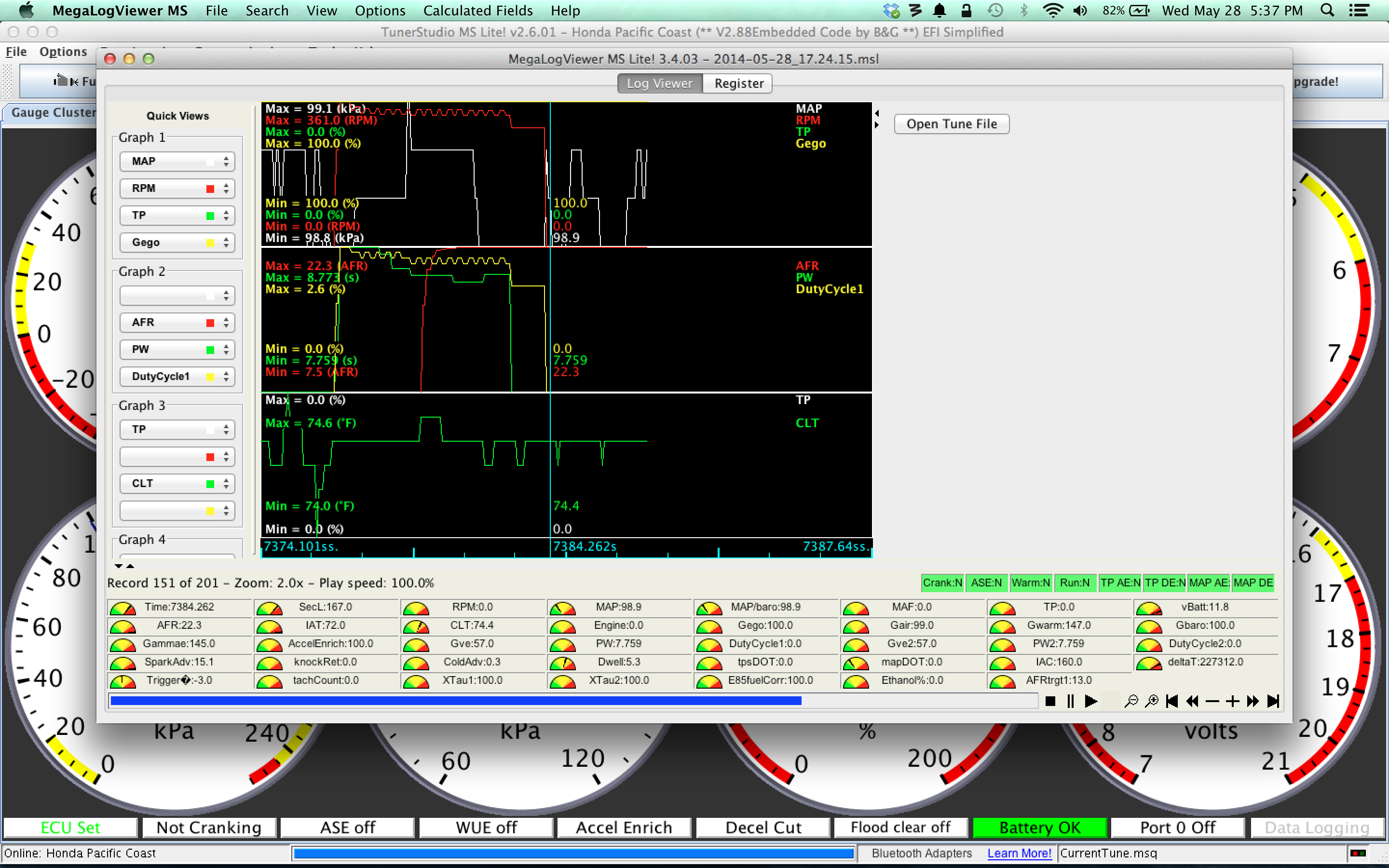 Above is a screen capture of a log file that I generated to see what RPM the engine cranks at. The average seemed to be around 340 RPM. I think this is about correct although I’m not sure if the Pacific Coast’s stock ignition control unit operates in wasted spark mode or if it only delivers spark to the cylinder when it is the appropriate time for a spark.
One thing that graph doesn’t show but another graph did is that I have some serious voltage drop with the way the system is currently configured. Without running the high pressure fuel pump, I was seeing as low as 9 volts on the MegaSquirt. Hopefully that isn’t entirely accurate. It isn’t in the danger zone for forcing a MicroSquirt restart but it is pretty low for getting a good spark. More research will have to be done on this once I have the final pieces in place.
In other news, I found a Bosch P/N 0 280 140 551 idle air control valve that is a two wire PWM setup with spring return. The only problem seems to be that in the fully off state, the valve goes a bit too far and becomes partially open. There is a brass set screw that seems to set how far back the valve turns. However, it was sealed in place with some factory goop. After chiseling the goop out, I wasn’t able to get the brass screw to spin and instead was stripping out the hex keyhole. I think that I am going to try drilling the brass screw out and replace it with a press-fit pin that i drive into the correct depth. This wouldn’t be a problem if the MicroSquirt had stepper control built in. I might still go back to DIY Auto Tune and buy the stepper IAC mod kit for people with the DIY PNP MegaSquirt. I previously had an email conversation with the good folks at DIY Auto Tune about grafting one of those kits onto my MicroSquirt. It wouldn’t be easy but it is possible to do. On the other hand, I might find that I can tweak the tune well enough to have the PC800 reliably start without an IAC. Time will tell.
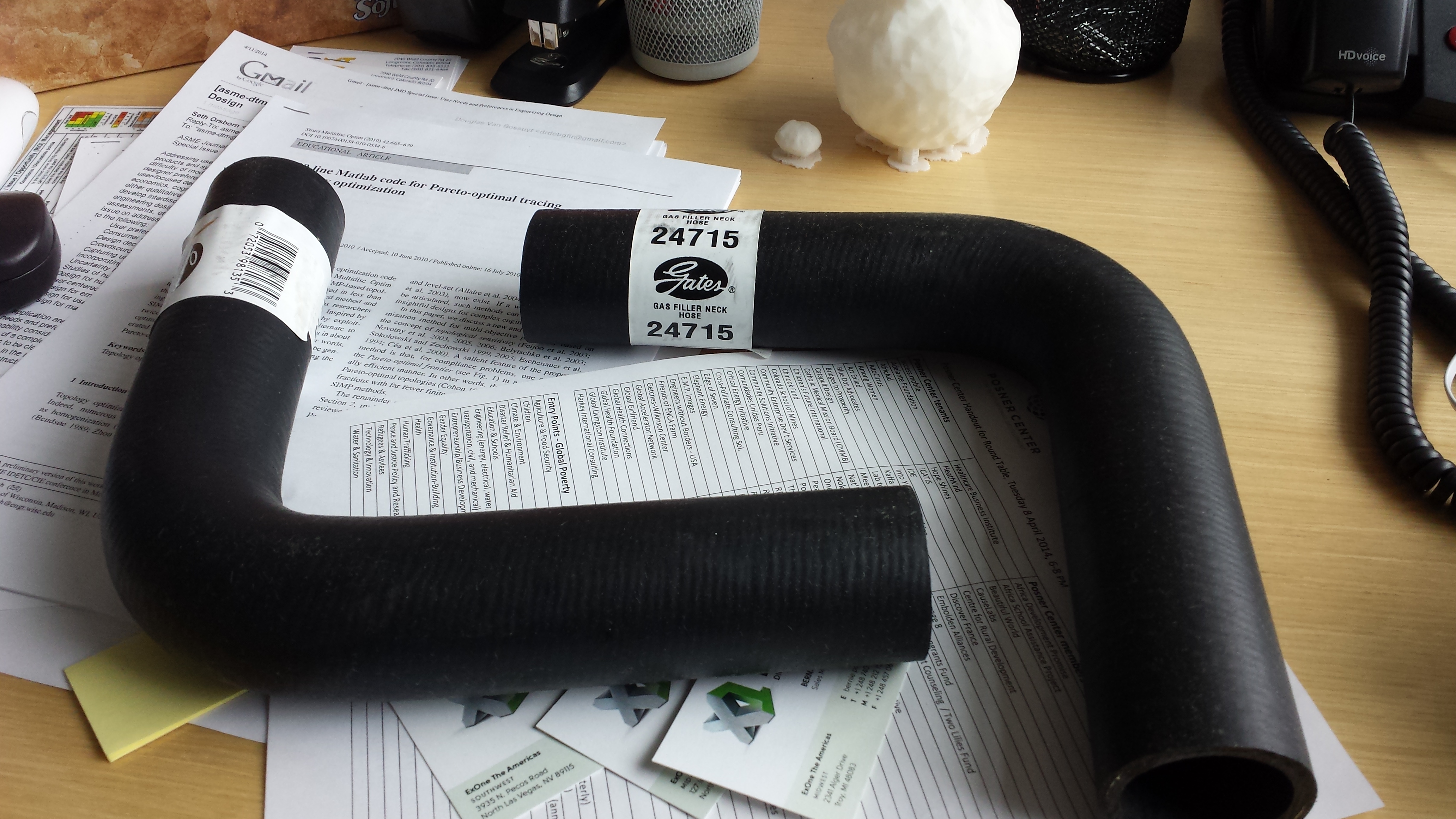
Up next on my to-do list is to bring the throttle body assembly to the university with me to try using the 3D scanner to capture CAD geometry data. I am planning to develop a custom adapter to go between the throttle body and the engine intakes. As luck would have it the rubber carb boots from the PC800 are the correct size to fit on the VTX1300C throttle body. I plan to design the adapter in a CAD package, 3D print a prototype in plastic to check for fitment, and then send out to an additive manufacturing house for a 3D metal print.
On the spark control front, DIY Auto Tune is now making a quad spark control unit that is much less expensive than other alternatives. I only need to control two sparks but it would still work for my application. Then the issue would be dealing with the oddly designed pulse trigger wheel inside the PC800 crankcase. The MicroSquirt firmware isn’t really designed to support such an oddly shaped trigger wheel pattern. I would probably have to replace the existing trigger wheel with a custom wheel to make it easier to tune the spark. For now, I am sticking with the stock ignition control module. Maybe later I’ll get more ambitious and run spark off the MicroSquirt, too.
Progress is being made slowly but surely. I haven’t encountered anything insurmountable yet. It’s just a matter of slowly and methodically working on the motorcycle to bring it to life with fuel injection.