


I took the PC800 out for a spin around Asilomar today to exercise the bike. It was a pleasant, warm day along the Pacific Coast.

The personal and professional website of Douglas Van Bossuyt
I took the PC800 out for a spin around Asilomar today to exercise the bike. It was a pleasant, warm day along the Pacific Coast.
Another PCer came through Monterey on his way south on a rented bike so I tagged along with him all the way to the elephant seal vista point near San Simeon. We then went to Cambria for lunch before I turned back north.


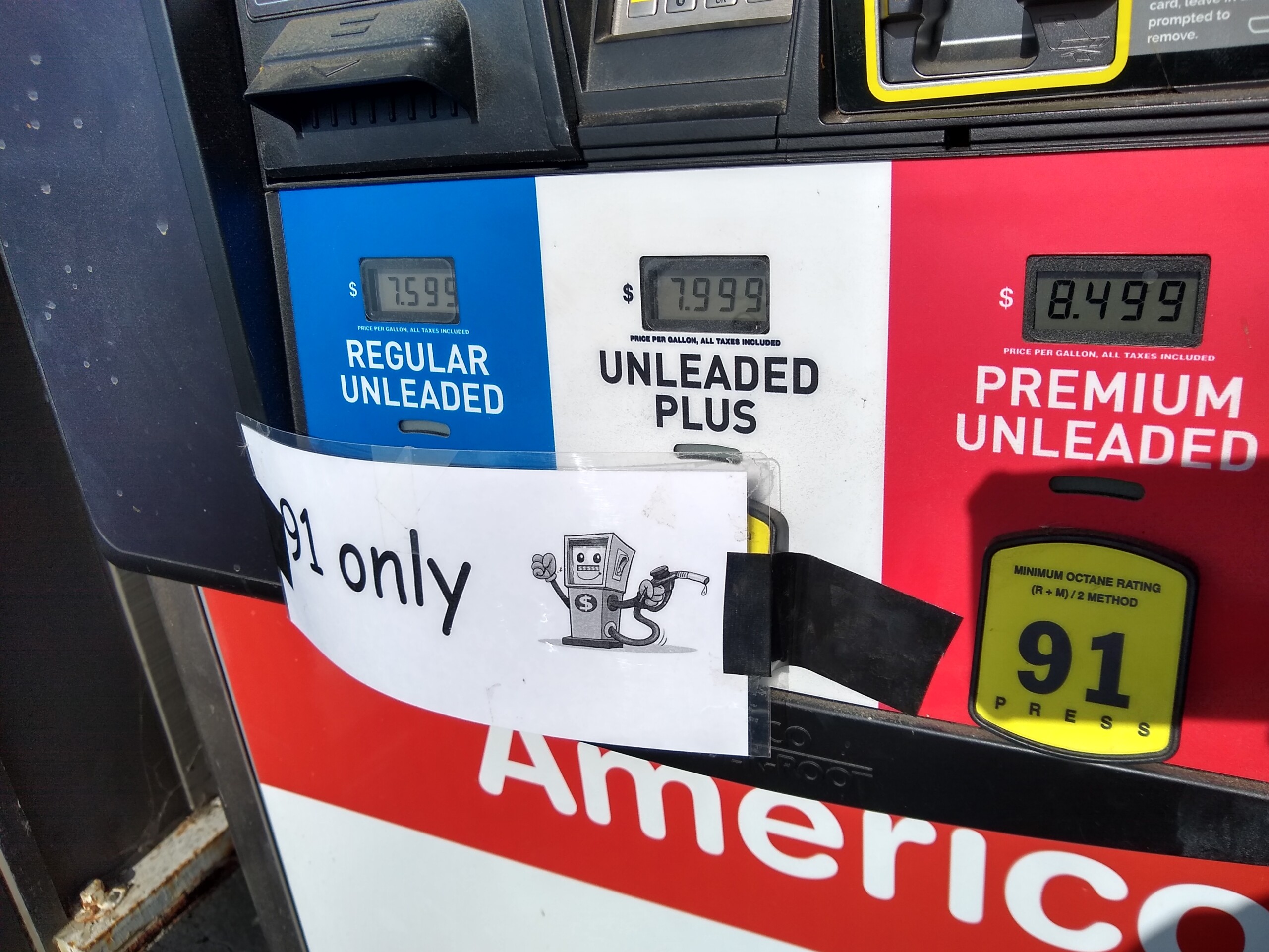
On my way back north I encountered a significant headwind that was rapidly depleting my fuel supply. Rather than chance it getting to the next gas station in Big Sur, I pulled over in Gorda to fuel up. This is one of the most isolated gas stations in the Lower 48 and the price really shows the isolation. They were out of regular and plus but they still had premium at $8.499/gallon. This photo even ended up on some nightly news show because the price was so high. Such is life along the Big Sur coast.
This page describes installation of a Shindengen SH847 series regulator/rectifier (R/R) on a 1997 Honda Pacific Coast (PC800). Results of various tests performed after installation are included.
Editor’s Note: The following information comes entirely from fellow PCer Seth. He did excellent research and produced a wonderful writeup of how to install a series regulator rectifier (R/R) on a Honda Pacific Coast.
This page describes installation of a Shindengen SH847 series regulator/rectifier (R/R) on a 1997 Honda Pacific Coast (PC800). Results of various tests performed after installation are included.
The R/R performs two functions: it rectifies the three-phase AC output from the stator to provide DC and it regulates the output to avoid overcharging the battery. The stock regulator is a shunt design which operates by short circuiting the stator windings when the battery is fully charged. The excess power is dissipated as heat by the R/R. The SH847 is a series regulator and operates by disconnecting the stator windings when the battery is fully charged.
Note: The SH847 isn’t cheap. Towing a trailer over The Mighty Mac up to The Very Boring Rally in Duluth, MN, without a charging system makes it seem worthwhile.
Having replaced all of the lights on Winglet, a 1997 Honda Pacific Coast (PC800), with LEDs there is plenty of power available for farkles: driving lights, heated lederhosen, Bushtec trailer, … . That is not what Mother Honda had in mind when the charging system was designed. The LED conversion greatly reduces the electrical load and shifts more responsibility to the regulator.
The stock R/R and, to a lesser extent, the stator are considered (by owners) to be consumable parts. The first is rather easily replaced. The second involves opening the crankcase and is, at best, a nuisance. (Been there, done both repeatedly, didn’t get the shirt. At least the engine doesn’t need to be removed from the frame like ‘oldWing’s.)
The series R/R design allows the stator voltage to rise, but reduces the load and the heat produced by the stator. High voltage is related to insulation breakdown, but so is elevated temperature. In my judgement the voltage (About 70VAC open cicuit, IIRC.) is not sufficient to significantly shorten the life of the stator and the lower temperature should increase the life. (Then there is thermal cycling causing physical damage to the stator and … .)
The plan is that this should be the last R/R and stator that Winglet needs. (This is what authors call “foreshadowing”.)
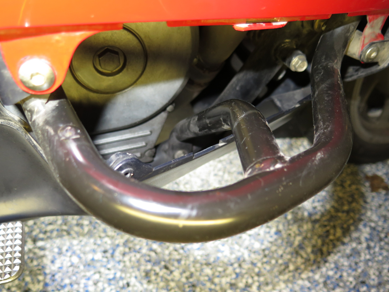
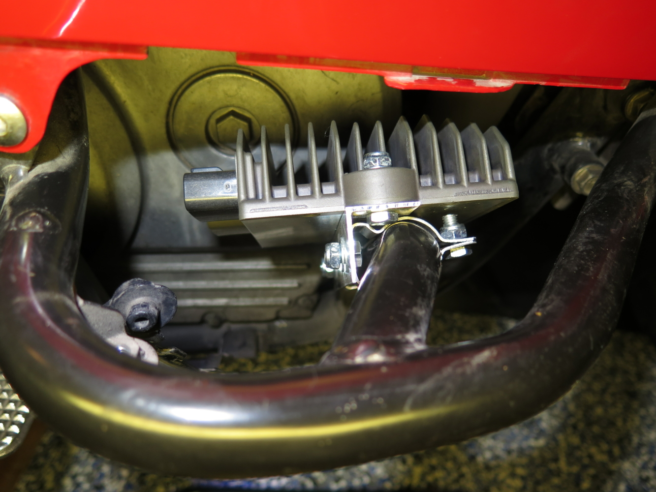
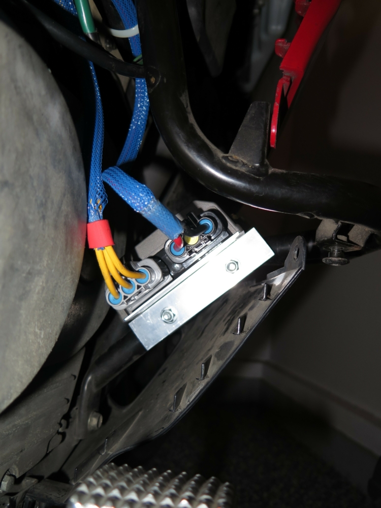
It’s big, but fear not. There is a splendid place to hide it if you haven’t tucked an air horn or other farkle in the right fairing protector. It mounts securely to the frame within the structure of the fairing protector, though it does not use the frame as a heatsink. The weathertight connectors face aft to reduce exposure to road spray. Engine heat and exhaust from the radiator ductwork are not problematic. Ideally the cooling fins would be oriented from front to back to provide better airflow, but there isn’t sufficient space to rotate the R/R with the connectors and cables attached.
Tip: Click on any image to open a larger version in a new browser tab.
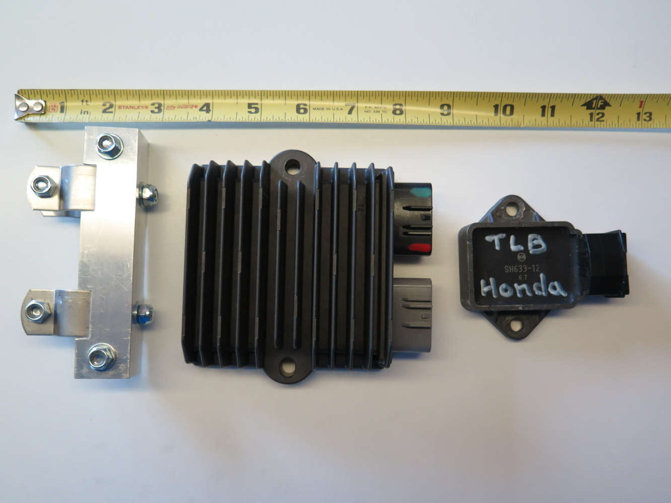
Despite considerable hunting, I have not been able to find a comprehensive specification sheet for the SH847 from Shindengen. The following specifications have been cobbled together, but are certainly not guaranteed.
| Property | Value | Note |
|---|---|---|
| Width | 120mm | 100mm between mounting hole centers. |
| Length | 135mm | Plus mating connectors and minimum bending radius for wires. |
| Thickness | 40mm | About 1 9/16″. |
| Current | 30A | Average @ 40°C (104°F) with no airflow. |
| “ | 37A | With 1 m/s (2 1/4 mph) airflow. |
| Peak Current | 50A | PC800 alternator maximum output is 360W or about 30A. |
| Protection | Voltage & Temperature |
Sources of supply are shown, but feel free to shop around.
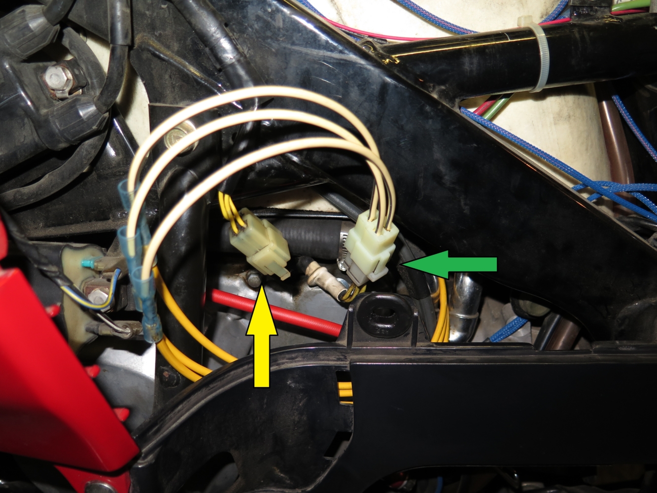
Note that installation of the SH847 leaves the original R/R and wiring in place. You can disconnect the SH847 and reconnect the stock R/R if there is some reason to do so, e.g. the frame is cold.
NB: Do NOT run the engine with both R/Rs connected to the battery at the same time.
You don’t want to find out if the overvoltage protection circuits in the two regulators get into an argument.
I don’t think they will, but with the price of Magic Smoke these days … .
Winglet was ridden with various electrical loads. It didn’t matter. The new R/R became lukewarm at most, but never hot. The stock R/R would have removed fingerprints in an instant.
The minimum load was without any accessories and all of the lights replaced with LEDs. With the stock R/R this would result in the maximum amount of current being shunted and thus the maximum heat generated. Aside: At idle with stock lamps and the brake lights on the battery would have been discharging. With LEDs that is not the case.
The following measurements were made with the ignition on and the engine not running. (For perspective, the stock headlight bulb draws 4.9A/5.4A.)
| State | Total Load | Note |
|---|---|---|
| Headlight and running lights. | 1.91A | |
| + Driving lights on high. | 2.84A | Denali D2 LEDs. |
| + Brake lights. | 3.35A |
Maximum load was with a heated vest (about 45W), driving lights, Bushtec trailer and various minor accessories. (All of the trailer lights have been replaced with LEDs with the exception of the license plate lamp. It has wires soldered to the bulb and the bulb is glued in place!) Engine temperature was allowed to rise sufficiently to turn on the cooling fan.
The misfortune that followed provided an opportunity. Not long after installing the new R/R the Rick’s Motorsport Electrics stator installed about 15 years earlier developed a short to ground. (The original stator lasted about 8 years.) An ElectroSport stator was purchased and the experiment was planned. Various resources on the Internet suggested that a shunt regulator reduces the load on the stator when it shorts the windings. (Did you know the word “gullible” isn’t in the dictionary?) It seemed like a good time to get some objective data on stator temperatures under various conditions using shunt and series regulators.
Possibly applicable reading: Facts about shunt-based regulators.
Possibly applicable viewing: “Turbo Encabulator” the Original.
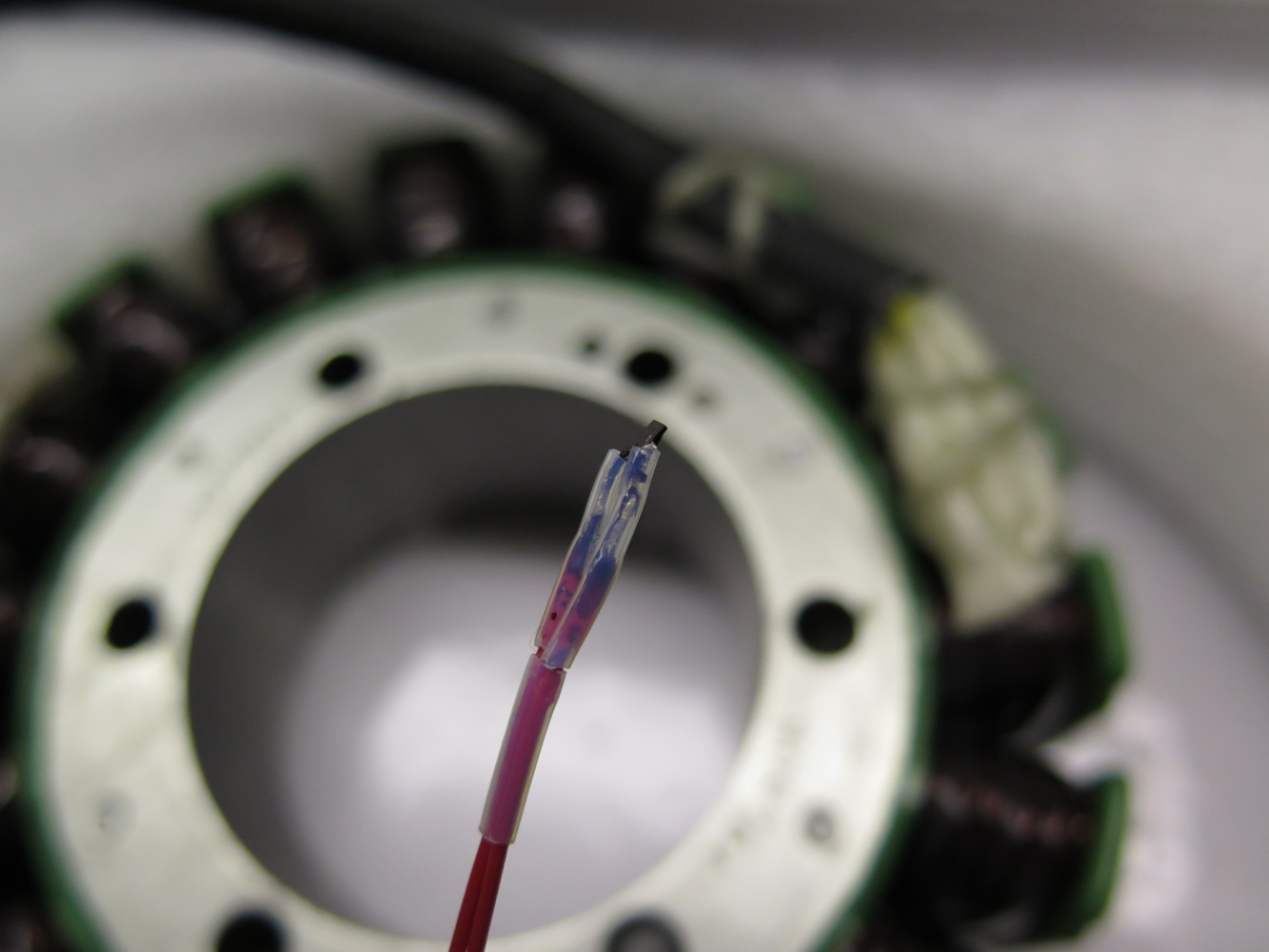
First, do no harm. I know that the stator is an unhealthy place with hot engine oil, hotter windings and machinery with a low tolerance for loose bits bobbing around. All of the materials going into that environment had to tolerate chemicals and heat. As a SWAG I chose 200°C (392°F) as a target temperature limit. The materials I obtained I dubbed close enough:
Did you catch it? I didn’t. I soldered the wires to the RTD with an 800°F tip in the soldering station. Applied the conformal coating and allowed it to cure. Put the heat shrink tubing on and cranked up the Milwaukee hair dryer to shrink it … . Shrink temperature 620°F. 60/40 Sn-Pb solder melts at 370°F. D’oh! A little creative rearranging and I managed to get the solder to do its thing while the tubing shrank. (“Hats back on gentlemen, an idiot!”)
Aside: While taking soldering/brazing/welding classes I caused some confusion when I used the Milwaukee variable temperature heat gun to sweat solder 3/4″ copper pipe and fittings together.
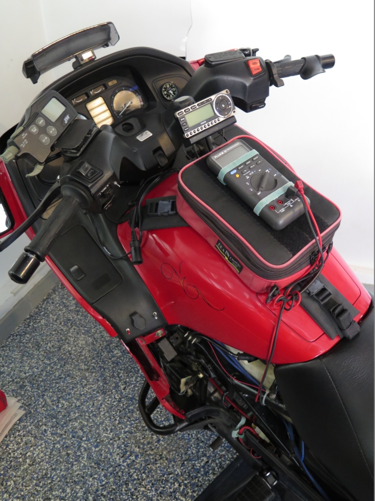
A Littelfuse PPG102A6 Resistance Temperature Detector (RTD) was embedded between poles of the stator prior to installation. A Fluke 87 Multimeter was used in Min/Max/Avg record mode to capture the temperatures.
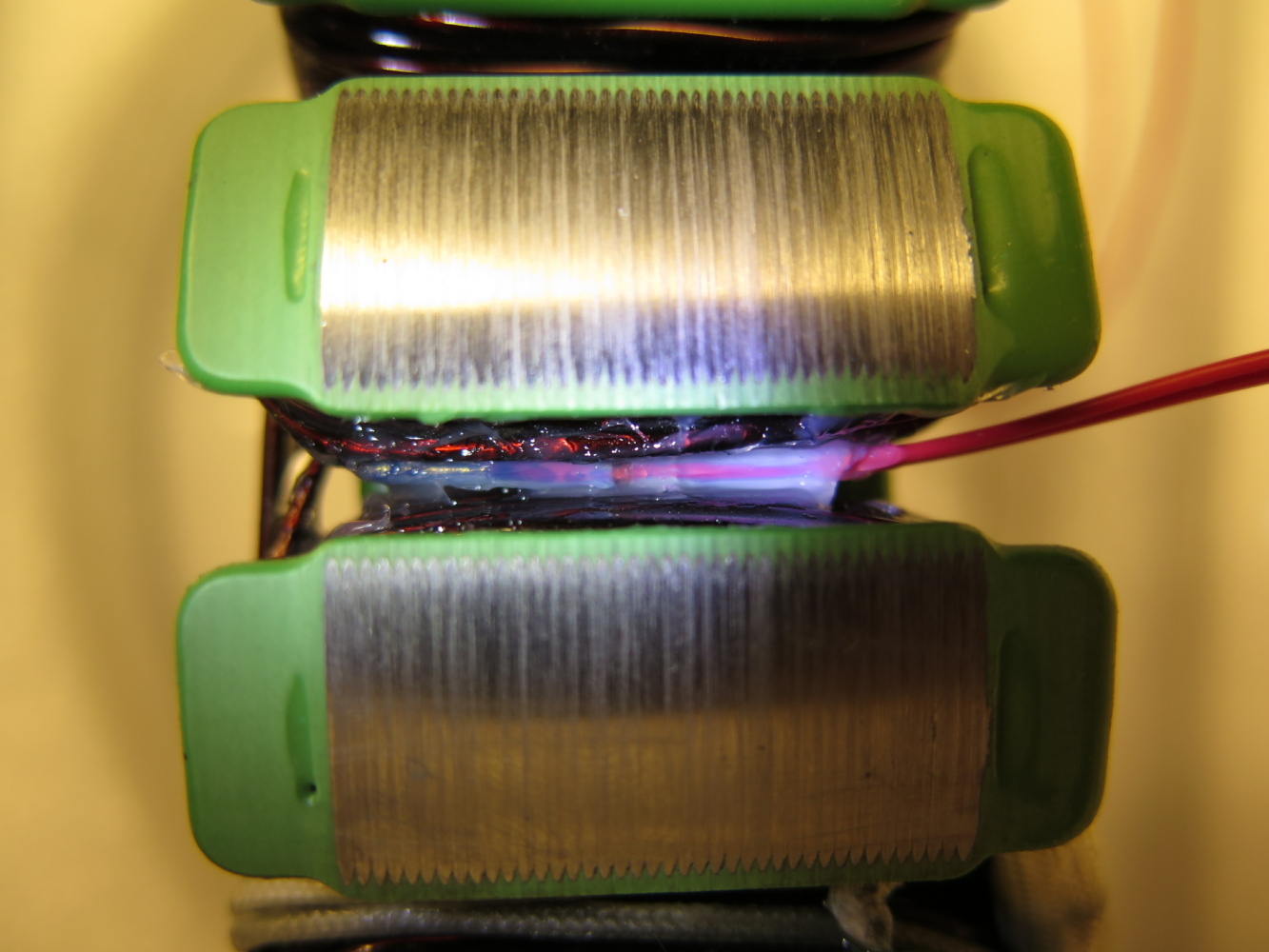
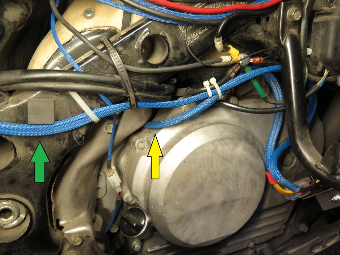
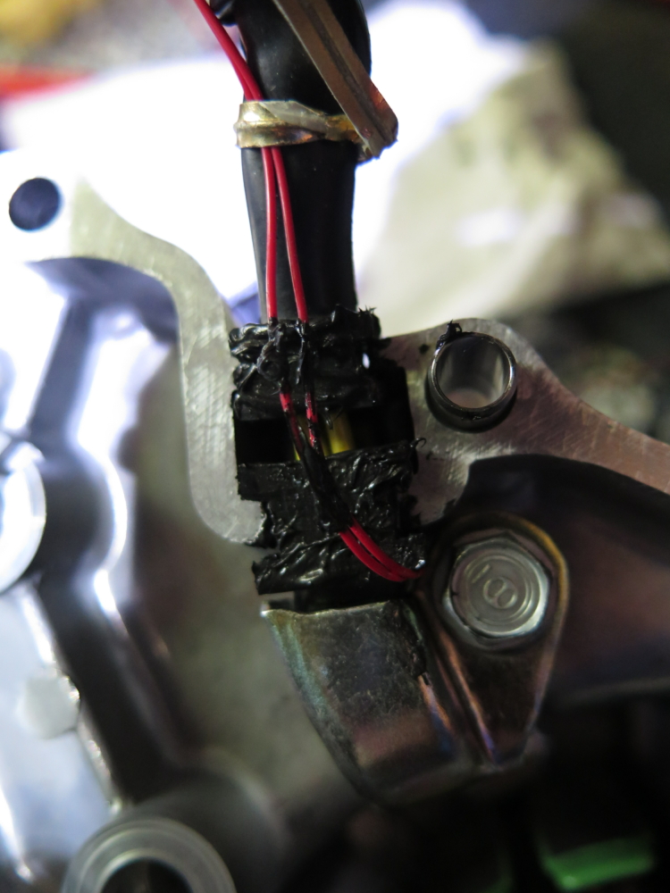
The wires were slipped through the jacket that protects the stator wires. Rather than make changes to the crankcase cover or seals I simply ran the wires out between the cover gasket and the cable seals. A generous dab of Permatex® Ultra Black® gasket maker is working nicely.
At idle the series regulator supplied <= 3.75A.
Started the engine and allowed it to idle until the fan cycled on and off. 72.6°F ambient temprature, 71°F stator before starting.
| No Regulator | Shunt Regulator | Series Regulator | Delta (Shunt – Series) | |
|---|---|---|---|---|
| Fan start: | 136°F | 198°F | 170°F | -28°F |
| Fan stop: | 139°F | 200°F | 171°F | -29°F |
| Maximum: | 140°F | 203°F | 173°F | -30°F |
The engine was then run at higher speed (~3K) and the maximum temperature noted:
| Shunt Regulator | Series Regulator | Delta (Shunt – Series) |
|---|---|---|
| 228°F | 212°F | -16°F |
Additional tests were run during sustained operation at highway speed.
The first test was run with the shunt regulator to give it the benefit of a cooler initial temperature. The second test was run with the series regulator.
| Shunt Regulator | Series Regulator | Delta (Shunt – Series) | |
|---|---|---|---|
| Maximum: | 288°F | 253°F | -35°F |
| Minimum: | 251°F | 240°F | -11°F |
| Average: | 272°F | 248°F | -24°F |
Conclusion: The series regulator lowers the stator temperature under all of the test conditions.