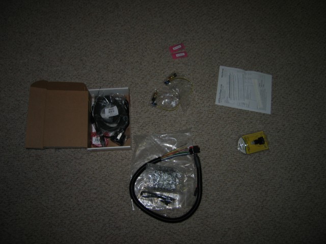
The electronic parts for the fuel injection project arrived on Monday. The MicroSquirt, wide band O2 sensor and gauge, air pressure sensors, thermal sensors, and USB to serial cable all showed up as expected.
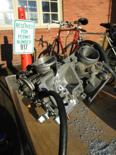
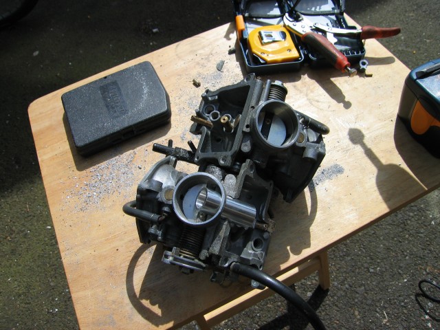
I finished drilling out the holes for the injector bungs earlier this week.
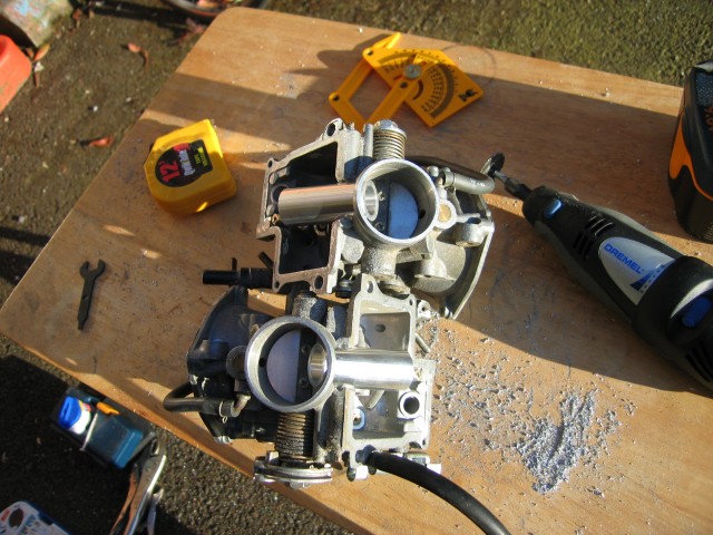
The bungs slip in nicely and are at about the same angel and position. I plan to JB Weld them in once I have built injector bosses and made adequate provisions to secure them to the carbs.
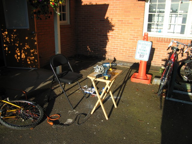
This is my outdoor work space. A Dremel too, cordless drill, and some sunlight are all that I need. Sure would be nice to have a drill press or mill though…
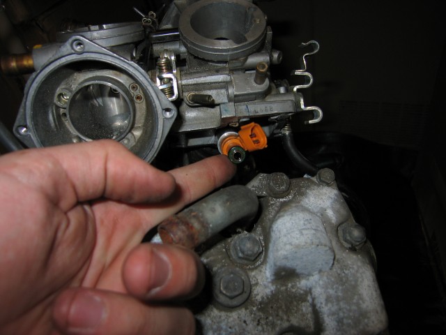
Here is an injector in the bung on top of the test engine that Bart is loaning me. It fits with plenty of room to spare. The injector boss should fit fine on top of the fuel injector.
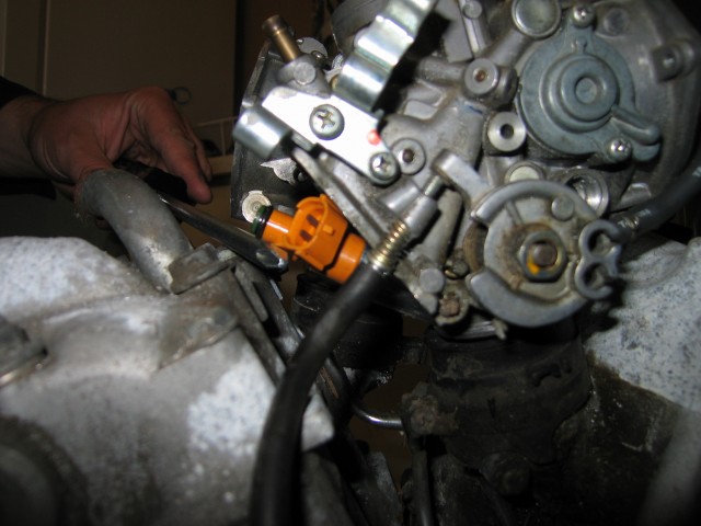
I’m using a screw driver to hold the injector in position.
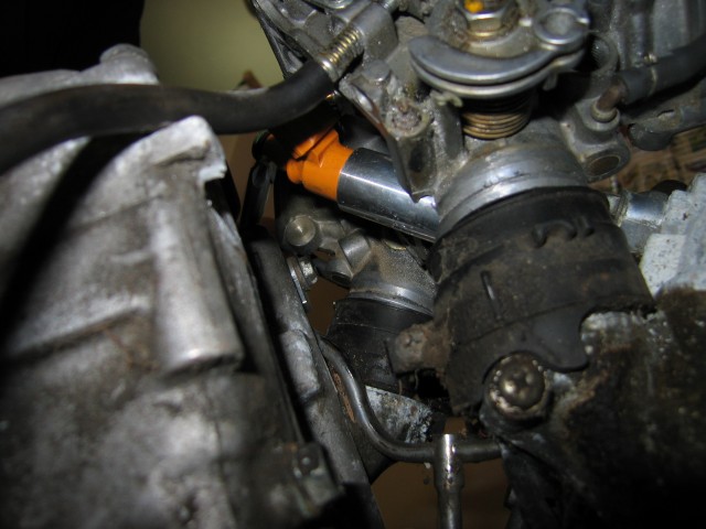
The next steps is to build the injector bosses that will carry pressurized fuel from flexible fuel lines (most likely rubberized) to the injectors. I plan to do that using brass and a mill. I believe I will put NTP threads on the end that will connect to the fuel hose. Need to go to an auto parts store and figure out the most inexpensive and safest fittings that I can use. I will purchase other miscellaneous fittings at that time as well. Another thing I need to do is purchase a fuel pressure gauge. I plan to purchase a digital (so high pressure fuel isn’t snaking up into the dash) pressure gauge to mount on my dash. Most likely it will come from Gaffrig Performance as their units are fully waterproof.
In order to hold the TPS in place, I plan to get a thin aluminum plate that I will mount it to. The plate will serve as an adapter to allow me to mount it to the carbs in such a way that it will not interfere with the throttle cables. I will have to machine a part to extend out the nut that connects to the shaft around which the butterfly valves rotate. The first part is doable with a Dremel and hand drill. The second part might require me to get time on a lathe. I have a few ideas on how to do it by hand though.
The fuel tank still needs to be modified. I’ve been dragging my feet on this one a bit. It really *should* be welded rather than just using JB-Weld to guarantee that it won’t fail down the road and dump gasoline all over the exhaust system. There is the guy in town who said he can probably do it. Maybe next week I’ll give him a call again and take the tank to him for his assessment. A friend with a MIG welder said he might be willing to give it a shot, too. I don’t want to blow any of my friends up though 🙂
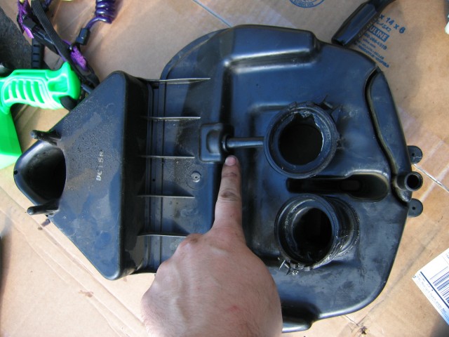
Modification of the air box for the MAP and IAT sensors will start soon. That shouldn’t be too hard to do as the air box is plastic and the sensors are pretty forgiving. The extra air box I bought is ready and waiting for what tortures I have in store.
I will need to fab up some brackets to mount the tip-over sensor. Not sure exactly where I’ll put it. Maybe somewhere up in the cowl. I also need to decide if I want to purchase a knock sensor or not.
Sooner or later I need to invest some more time in reading about spark control. I’m not sure if I need to buy additional components or if I can use what is already on the bike. Hopefully nothing additional needs to be purchased.
The O2 sensor bung is going to be a pain to weld in place. The friend with the MIG welder said he’d take a shot at it if there is enough room for his tool. I want to weld it on the exhaust accumulator that lives directly underneath the fuel tank. I plan to weld the bung in place when I drop the tank and rear wheel out. Speaking of the rear wheel, I am in dire need of a new tire. Hopefully I can get that on sooner rather than later.
This project is, I would say, about 1/3 to 1/2 way done. Momentum should be picking up quickly as almost all of the parts are in and modification is going smoothly. It’s just a matter of finding the time and the few odd scraps of metal I need to finish this up.
