Note: This project started in February and just finished at the end of May. It took me a while to figure out where to put it, how to configure it, etc. In retrospect, it might have been easier just to throw the whole thing in my trunk and call it good. But hey, this approach was more fun!
First before I describe this modification to my motorcycle I should warn you: there is no reason to do this. You can buy any number of products for under $100 that do the same job and don’t require hacking. That said, I did it because I wanted to hack something together and be a little unique.
Disclaimer: This mod is dumb and dangerous. You shouldn’t do it. If you do, you might die, be horridly maimed, kill your little brother’s kitten, and destroy half of a country along the way. The things I am doing are potentially dangerous. Electricity is involved. A brushed DC motor that makes sparks is involved. This thing mounts near a gas tank where there could be vapor and fumes. I wouldn’t recommend you try this. DO NOT TRY THIS AT HOME. YMMV.
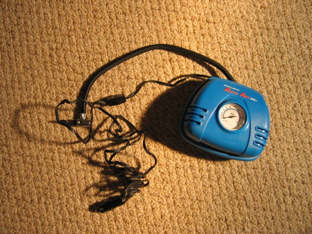
At one of the local auto parts stores I found a “MidAtlantic 12 Volt Auto Air Portable Air Compressor.” The packaging states that it is “for every tire emergency” and that it goes to “250 PSI.” I can confirm that it will go to 250 PSI, however it will take a looooong time to get there if the volume of space you’re filling with air is large. You can find this compressor online for less than $15. For instance, this place sells it. No clue if that site is any good to buy from or not but you can see what it looks like in the packaging anyway
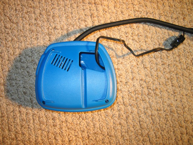
Here is a shot of the back side of the unit. There is a LOT of dead space in the packaging where you are supposed to put the 12 foot really flimsy power cord. This got me thinking… Why not take the case off and make the whole assembly smaller?
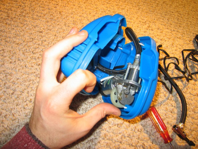
Here is my first view of the guts. That little piston is TINY. It has less volume than a shot glass. The air intake is a little hole with a flapper valve of some sort at the top of the stroke. There is a similar setup inside the piston to let the air out on the compression stroke. Four screws hold the case together. It took a little bit of time to work them out of the plastic. They seem to be self-tapping screws.
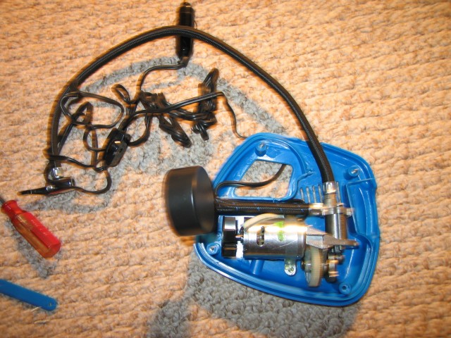
Here it is taken halfway apart. I can’t impress upon you enough how poor-quality the cable is that comes with the unit stock. The switch is really, really lousy. It fell asleep after the first time I tested it out in my car. Good thing we won’t be needing it!
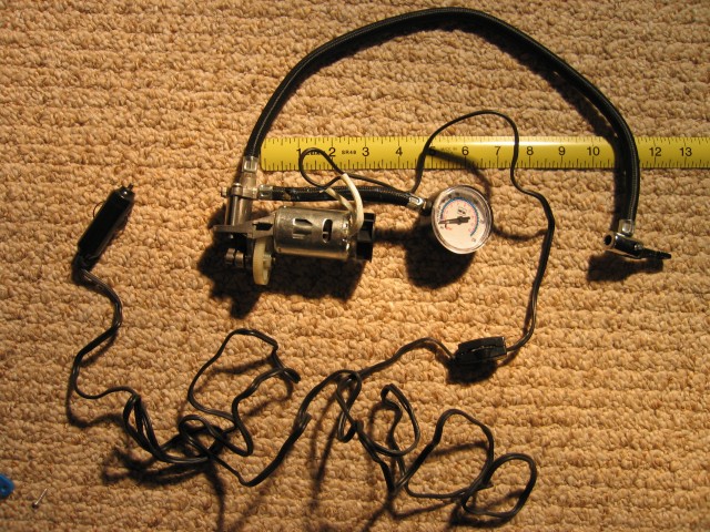
The measuring tape is so you can get an idea of the size. This unit is SMALL. So small in fact that it will fit between the trunk wall and the gas tank on the left side of a PC800. Do I smell a cool bike mod? Why, yes I do! I should also note that it was a bit difficult to get the compressor and motor assembly out of the blue plastic case. It was held in with a metal band that was screwed and glued down. I ended up cutting the metal band in half to get it out.
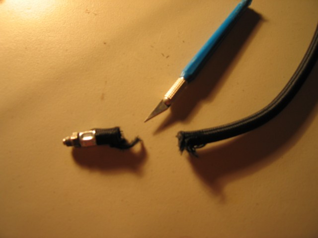
The first step to a successful project is to do something that makes it so you can’t return the unit. I cut off the end of the hose that came with the compressor. An Exacto knife or box cutter should work just fine. The inside of the hose is rubber similar to what radiator hoses are made out of. Be careful to not let the hose braiding cover to come undone. A bit of electrical tape can help keep it together if it is unraveling too fast.
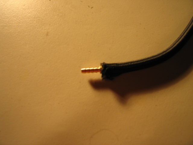
Over at the local home improvement store I found a nice 3/16″ to 3/16″ hose barb that fit snugly into the rubber hose. The hose probably could have fit a 1/4″ barb however the hose I found to attach to this barb wouldn’t take that large of a barb.
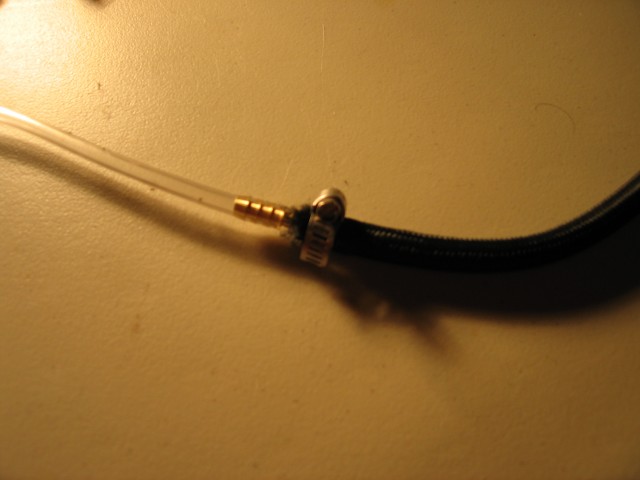
Using a tiny hose clamp seemed pretty reasonable to me. After tightening it up, that rubber hose isn’t going anywhere. On the other side of the barb I attached a 10 foot long vinyl tube. The OD of the tube is 1/4″ and the ID of the tube is 0.170″. The particular type of vinyl hose I found is rated for 55 PSI which is well below what this little pump is supposed be able to achieve. However, there is NO WAY that this thing will ever reach that pressure when this thing is hooked up to a tire. And if it does pop… well, then I learned my lesson.
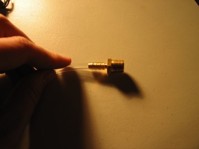
This is the other end of the vinyl hose. I put a 3/16″ hose barb to male 1/4″ NPT fitting on it. The thing is nice and snug on there and won’t be going anywhere.
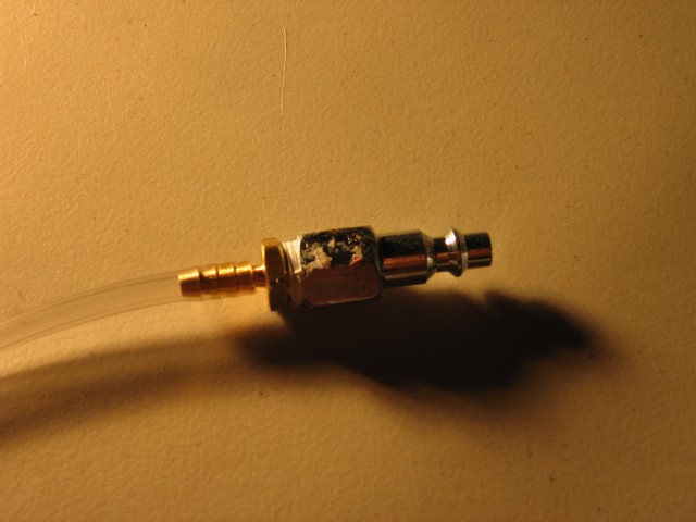
Next I attached a quick-disconnect coupling. This isn’t strictly necessary but I figured I might as well so I have the option of disconnecting the hose from the pump to store it separately on the motorcycle.
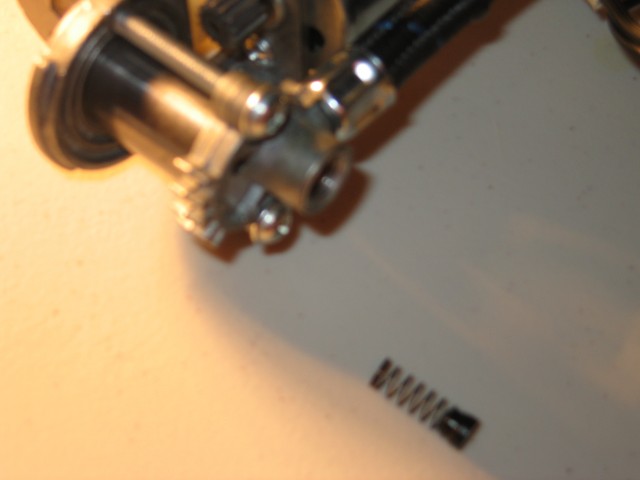
When you take off the stock hose from the pump, this little spring and plug will pop out. In this picture the spring/plug is flipped 180 degrees from where it should be. Don’t lose this thing! You need to put it back in when you’re putting the new fitting back on.
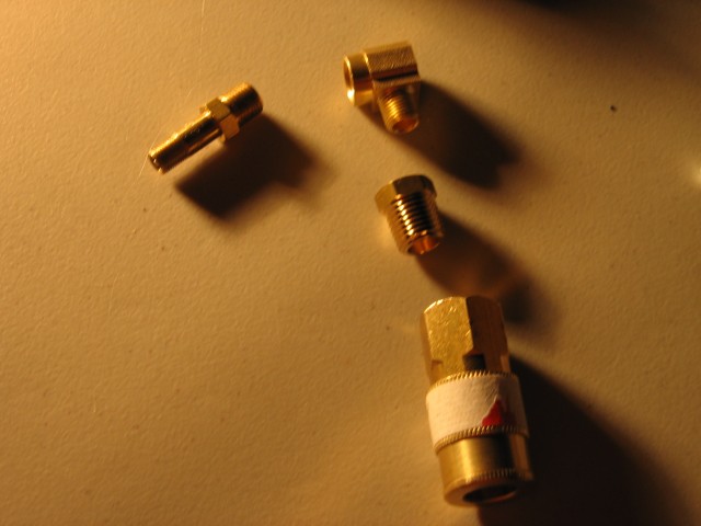
This is the assembly of parts that I put together to be able to attach a different hose to the pump. Starting at the upper left… The fitting connection on the pump is a Schrader valve size. It’s a real oddball and most people will have NO CLUE what it is. It took me the better part of a day to figure it out. I finally found a perfect-ish solution. The local auto parts store had an “Industrial Tank Valve” that goes from 1/8″ MNPT to Schrader. It is meant to be used on a pressure tank so that it can be drained of water or be filled with air or whatever. If you can’t find it at an auto parts store or hardware store, try an industrial welding supply or industrial gas company. Be sure to take out the valve core before you assemble it.
The next part is a 90 degree elbow that has 1/8″ NPT threads on each side. Following that is an adapter to take it from 1/8″ NPT to 1/4″ NPT. This allowed me to attach it to a quick disconnect coupler. I put some plumbers tape on everything and tightened it all up. The only other thing that I’d like to add to this assembly is a relief valve. If you accidentally turn it on without a hose attached, the pump will quickly shoot past 250 PSI and put the unit in danger of explosion. Perhaps if I can find an inexpensive valve I’ll throw it into the mix.
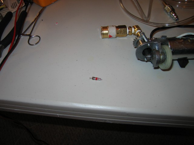
That valve core in the middle of the photo came out of the Schrader to 1/8″ MNPT adapter. I was able to get it out with a pair of needle nose pliers.

Here is the assembled unit. I also attached a simple on/off switch to the wires. Note that you shouldn’t put a big halogen lamp close to the gauge. I managed to warp the gauge face (a piece of plastic) due to the heat. Oops! To this point the entire project cost me $40.
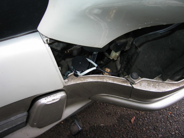
Now comes the fun part. I had to figure out where to mount this thing! The first option is down by the fuel pump and gas tank. The space is just a *little* bit too small. Also the idea of having a brushed DC motor running next to gas tank and fuel pump made me a bit nervous. All that space down there though got me thinking about stashing other emergency supplies there. Perhaps there will be another post about that in the near future.
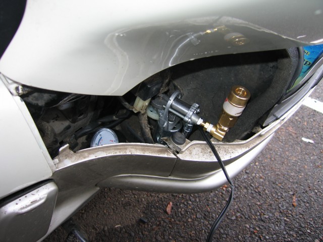
This location is marginally better but still dangerously close to a potential vapor source. Also the brass fittings get in the way of closing the trunk. And the gear/piston/motor exposed moving parts rub against an important-looking wiring harness.
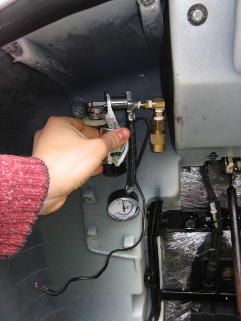
The top of the trunk looks pretty promising. I’d lose a little bit of storage space but gain a compressor. Also it’s nice and close to my tire patch kit and the auxiliary fuse box.
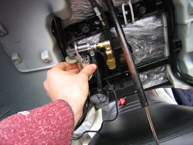
Under the seat would be a great place except for the bottom part of the trunk. The poor pump would get smooshed if I had it located there. Surely there must be SOMEWHERE I can tuck this thing out of sight until I need it. One place that I won’t put it though is in the front fairing. There is too much heat running around up there. Also I’m a little worried about unbalancing the front end by putting weight on one side or another. In addition, in a crash where the front fairing might get mashed, it could take out the pump when I might need it most. If I had a top case, I could stick it in or on that but so far I haven’t found a rear rack to mount a top case on. Someday… someday…
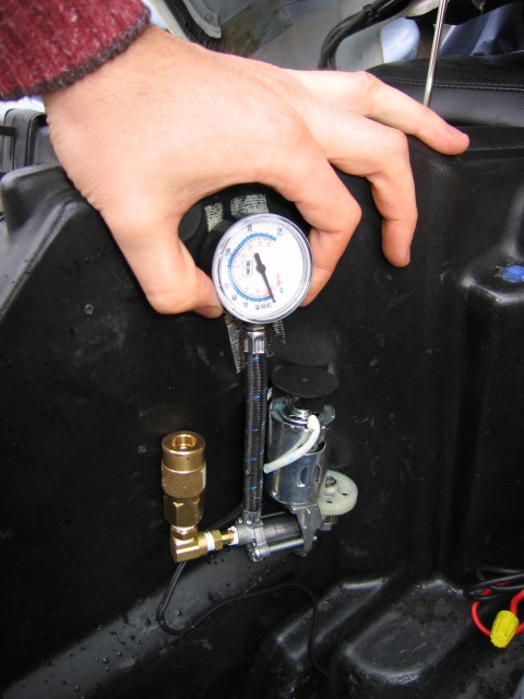
Another potential place to mount it in the trunk. If I put it here, I’d cover the moving bits with a piece of tin or plastic. I hate to take up trunk space for this thing though. Am really hoping I can find somewhere to put it on the bike that is not the trunk.
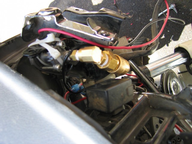
And then the perfect spot presented itself while I was replacing the radiator hoses… Behind the front fairing hanging off of the left mirror bracket!
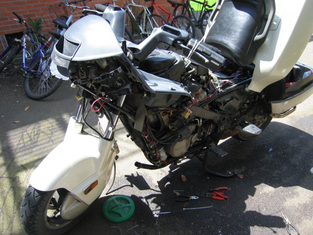
The unsuspecting mirror bracket is just waiting to have something hung from it. Poor thing. It never knew what hit it.
The compressor zip-tied in place. It will hold well enough for several thousand miles. At that point I’ll probably take the fairing off again for some other upgrade or maintenance issue.
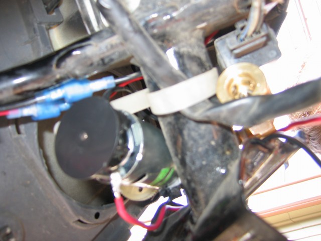
An upside-down view of the compressor zip-tied to the bracket. The red and black wires are the power wires for the compressor.
Looking up from underneath. The little fan might do something… Maybe. Yeah, probably not.
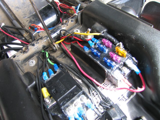
I ran the power wires back to my custom fuse block in the trunk. Also notice the switch hiding behind the yellow wire in the top middle of the photo. That controls the compressor. Flip it on and the compressor starts humming away. The switch is quite robust. I doubt I’ll ever have a problem with it accidentally turning on. The compressor is on its own 15 amp dedicated fuse.
I don’t have a photo of the setup for how I get a hose from the compressor to the rest of the bike just yet. This description will have to do… I routed the plastic tube that I had attached to the compressor around to the right side of the bike and out the right hand dash pocket/door thing that covers the radiator cap and overflow bottle. Behind that door I put a quick disconnect fitting on the hose. The other end of the hose with the pressure gauge and valve connector has the other side of the quick disconnect. It is stored in my trunk for when I need it. Having tried the whole installed compressor, I can say that it will in fact pump up a tire to the right pressure. It is best to have your back wheel off the ground when inflating it and if you can, get your front wheel off the ground for inflating it, too. That way you don’t run as much risk of burning out the itty bitty compressor.
In a year or so we’ll see if this configuration survived. For under $50 though, it isn’t that bad of a setup!
UPDATE: One year on and the system works great! I just aired up my tires yesterday. The gauge for some reason reads high but I’ve figured out what number corresponds to what pressure. Other than that, the compressor chugs right along whenever I need it. I just have to make sure that the bike is revved to at least 3000 RPM to keep from draining the battery. I can put about 5psi into either tire in two minutes. All in all, I would consider this mod a huge success.


