
Editor’s Note: I have replicated content here from Bruce Pickett’s old website. The content had gone offline some time ago and is only available in the Wayback Machine at this point. The content below is for historical purposes only. I cannot vouch for any of the information below.
These instructions reflect the efforts of Dave Steven, Chuck Chiodini, and Bruce Pickett to install the Audiovox CCS100 Electronic Cruise Control into each of their Honda Pacific Coast motorcycles. We would like to thank Alan Hall and Rick Corwine for their efforts in reviewing this document.
The authors of these web pages, and the owner of this web site, and anyone else associated with this project, disclaim any responsibility for any injuries to persons or damage to property that may occur by anyone using these instructions or any portion thereof. The users of these instructions bear full responsibility for their use.
Introduction
When riding on long stretches of roadway, motorcyclists often find it convenient to relax their grip on the throttle handle and rest their hand. Many PC800 riders use the Throttlemeister and Vista Cruise throttle locks, or the Throttle Rocker wrist rest, because these are easy to install and inexpensive. But while these devices have their places, they don’t really substitute for a cruise control, because they will not by themselves maintain a bike’s speed constant over varying terrain. And while there are some specialty cruise controls, such as the MotorCycle Cruise from Australia, there aren’t many, and they tend to be expensive – in the range of $500US.
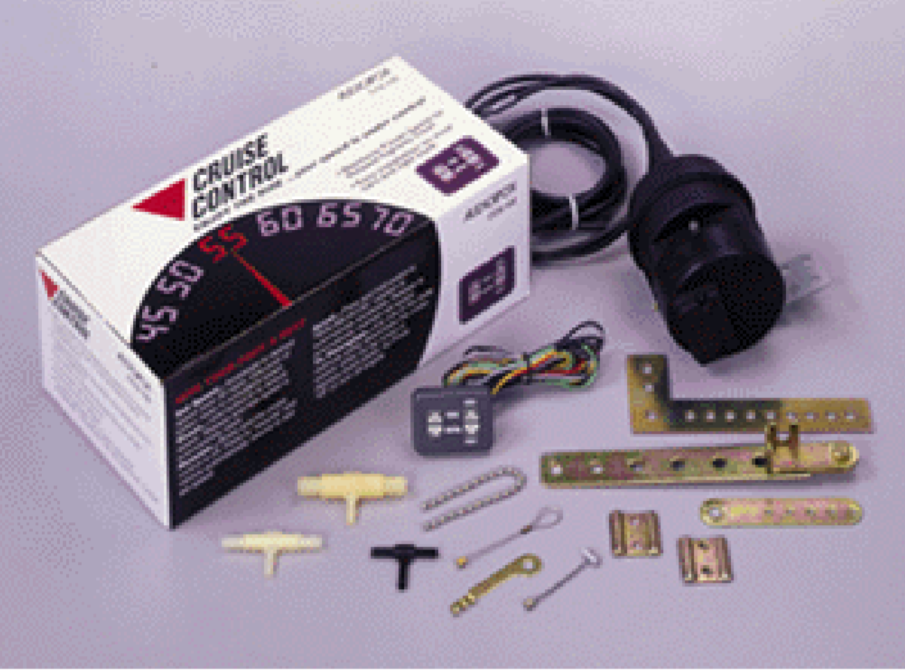
But cruise controls for automobiles abound, and they cost as little as a Throttlemeister throttle lock – however, the instructions for these do not accommodate installation on motorcycles. Some motorcyclists have experimented with adapting automotive cruise controls on their motorcycles with good results. But only a few people are known to have tried this for the Honda Pacific Coast PC800. These instructions detail the process of installing an Audiovox CCS100 electronic cruise control on the PC800.
The Audiovox CCS100 is available in many auto parts stores such as Schucks, Pep Boys and JC Whitney. The CCS100 kit contains numerous parts, many of which are not needed for the PC installation. Some of the kit’s parts may be modified for use on the PC800. A few minor parts must be purchased but these items are low in cost and are available from most hardware or auto parts stores. The major departure from an automotive installation is the need for a vacuum canister (made from PVC pipe) and the fact you don’t need to install any magnets or pickups.
Materials
- 1 – Audiovox Model CCS100 cruise control kit
- 2 – U-bolts, 3/4″ dia. x 1-1/4″ long x 1/4″ thread
- 1 – commercial vacuum canister (Audiovox p/n 250-6019, available from JC Whitney), or
- PVC or ABS pipe
- PVC or ABS end caps
- 1/8″ hose barb to ¼” MIP adapter
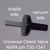
- Emissions check valve; NAPA p/n 730-1347
- PVC or ABS cement
- Electrical tape
- RTV silicon sealer (clear)
- cable ties
Preparations
Read everything before doing anything!
Remove plastic body panels:
Alternative 1: For Servo Installation In Right Roll Bar Cover (Fairing Protector)
The following plastic body panels must be removed regardless of which servo mounting location is chosen. Additional panels must be removed for mounting the servo in the Left Front Upper Cowl (see Alternative 2).
(numbers in parentheses refer to panel numbers in the PC800 Service Manual)
- Air Duct/Maintenance Lids (#10)
- Side Covers (#11)
- Right Fairing Protector (#7)
- Center Covers (#4)
- Top Shelter (#5)
- Handle Center Cover (#22)
- Handle Upper Cover (#23)
Alternative 2: For Servo Installation In Left Front Upper Cowl
In addition to the panels removed for Alternative 1, the following panels must be removed (numbers in parentheses refer to panel numbers in the PC800 Service Manual):
- Mirrors (#1)
- Wind screen (#2)
- air duct grill
- garnish
- frame
- screen
- rubber seat
- air duct
- Meter Panel (#9)
- Meter Visor (#6)
Removal of the following additional panels may make it easier to install the cruise control system, although it is possible to do the installation without removing them:
- Fairing Protectors (#7)
- Front Lower Cowl (#8)
- Front Upper Cowl (#3)
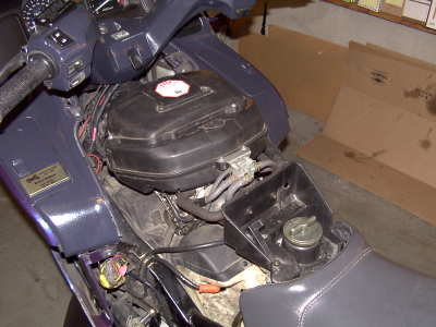
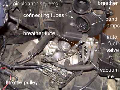
Remove the air cleaner housing assembly:
- remove 2 self taping screws holding the auto fuel valve to the housing
- loosen the connecting tube band clamp screws on each carburetor intake
- loosen the spring clamp on the breather tube at the rear of the housing and remove the breather tube
- lift the assembly out of the way
Vacuum System
Note added 12/29/01 – A ready-made vacuum canister may be purchased from JC Whitney. This VC is compact and provides all of the vacuum reserve necessary for the CCS100 on the PC800. An alternative method for installing the servo and JC Whitney VC together inside the left fairing is available here. [EDITOR’S NOTE: the old link is long since dead and I can’t find a copy of it.]
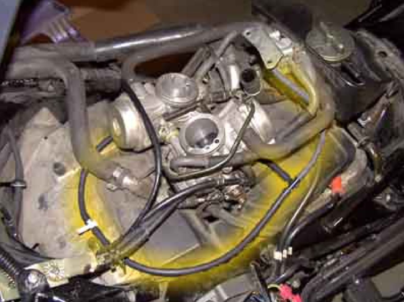
The CCS100 cruise control requires a constant source of vacuum. Vacuum is what supplies the mechanical power for the throttle actuator. The Pacific Coast’s two carburetors each have a vacuum source. The vacuum source on the #1 (left) carburetor is used to provide vacuum to the auto fuel valve; however, the one on the #2 (right) carburetor is normally unused and is capped off. Some PC800 cruise control installations have used both carburetor vacuum sources in order to capitalize on all vacuum available, however, several installations have utilized only the #2 vaccum source, and this has been demonstrated to more than adequately supply all of the system’s vacuum needs. While these instructions describe how to connect to both vacuum sources, it is recommended that only the #2 carburetor vacuum source be utilized, since it is a simpler installation and there is less opportunity for leakage because of fewer joints.
When a vehicle is using cruise control while traveling up long hills, more suction is needed for the servo to pull the throttle further and harder. On vehicles with larger engines, there is often enough suction available to provide all the needs of the cruise control servo without needing assistance. But on small vehicles such as the PC800, the meager suction provided by the carburetors can easily be overcome by hard pulls, causing the cruise control to slacken off. Consequently, the PC800 needs the assistance of a vacuum reserve. The vacuum canister (VC) provides this extra vacuum reserve to help the CCS100 maintain a constant pull.
Since there is limited space within the PC800’s fairings within which to mount equipment, the size of the vacuum canister will be limited in order to fit inside. Since it may be impractical to install a single, large volume vacuum canister, if more vacuum reserve is needed, two or more smaller vacuum canisters may be connected in series with additional lengths of vacuum tubing. Also, it is not required that the vacuum canister be located next to the servo; they could be separated by several feet, as long as there is sufficient length of vacuum tubing.
Making the Vacuum Canister
Ready-made vacuum canisters that include internal vacuum check valves are available at many auto parts stores that sell cruise controls kits – JC Whitney, a major catalog auto parts retailer, sells one for less than $10US. The JC Whitney vacuum canister is about 4 inches in diameter and about 5 inches long, with an internal volume of about 60 cubic inches. This VC has been used with very good results on the PC800, but because of its large diameter, finding a location big enough to accommodate it within the PC800’s plastic may be a challenge. You can also make one from parts readily available at hardware stores.
PVC or ABS plastic pipes and fittings can be readily used to fabricate vacuum canisters of nearly any size. Carefully measure the space where the vacuum canister will be located and size the parts accordingly, for there is very limited space within the PC800’s fairings. The volume of a cylinder may be calculated with the formula:
where:
V = volume;
p = Pi = 3.1416
D = diameter; and,
L = length
Some common VC dimensions are:
| Inside Diameter | Length | Volume |
| 1.5″ | 10″ | 18 c.i. |
| 2″ | 10″ | 31 c.i. |
| 3″ | 10″ | 70 c.i. |
| 4″ | 5″ | 60 c.i. |
Drill two holes in the end of one of the end caps that are sized appropriately for the adapters that you are using. Dry thread the barbed adapters into the holes so that threads are cut into the plastic. Remove the adapters and clean off any loose particles. Apply JB Weld to the new threads in the cap holes and reinsert the adapters, tightening them down flush. Apply additional JB Weld to the adapter threads inside the cap and ensure that they are well sealed to the cap. Make sure that air will flow through the canister unimpeded. Allow the JB Weld to set thoroughly before attaching the end cap to the pipe.
Cut a piece of pipe to length. Square the ends and clean off any loose pieces. Clean and prime the pipe and end caps. Cement both caps to the pipe ends with appropriate cement (i.e., PVC or ABS cement). Caution – do not test the air flow by sucking on the fittings by mouth – there may be toxic fumes inside the canister resulting from the glue.
The vacuum canister pictured above has an internal volume of about 18 cubic inches. If this does not provide sufficient vacuum reserve for the servo, multiple vacuum canisters may be constructed and connected in series. The picture below shows two identical vacuum canisters joined together by JB Weld and cable ties. A short piece of vacuum tubing connects the two canisters together to provide a total volume of 35 cubic inches for the vacuum reserve.
Here is an example of an even larger vacuum canister made from black ABS pipe and fittings. It has an inside diameter of 3″ and length of 10″, giving it a volume of 70 cubic inches. The construction methodology is the same as that of the canister with the white PVC pipes and fittings. This design attaches the vacuum check valve directly to the vacuum canister, thus eliminating one of the barbed hose connectors. A small hole was drilled into the end cap and the check valve was secured in it with JB Weld.
Attaching the Vacuum Canister
The vacuum canister is attached to frame struts under the front left fairing near the connection point for the left mirror. With the hose barbs on the vacuum canister pointed down and to the rear, attach it to the lower of the two fairing side struts with several long, sturdy cable ties. Make sure that there is sufficient space to attach the vacuum hoses to the hose barbs on the canister.
Vacuum Connections
Use the long rubber vacuum tubing supplied in the CCS100 kit. Additional tubing and fittings may possibly be needed, depending upon how many connections are made.
These instructions call for making connections to both carburetors’ vacuum ports. It is suggested that both ports are necessary to provide sufficient suction for the cruise control vacuum system. If, however, you choose to use only a single vacuum port, simpler connections may be made using only the #2 carburetor’s vacuum port.
Locate the capped-off vacuum port on the #2 (right) carburetor; this is an “L” shaped tube near the lower, front, right corner of the #2 carburetor. Remove the vacuum cap and its spring clip (you may want to save it for the future, “just in case”, but you don’t have to). Secure a length of vacuum tubing to this port – its length will be trimmed to fit later. If you will be using only a single vacuum port, this tubing can be run directly to the check valve and vacuum canister, and disregarding the following instructions for attaching to the #1 carburetor vacuum port.
Locate the vacuum port on the #1 (left) carburetor; this is an “L” shaped tube near the lower, rear left corner of the #1 carburetor. There will be an existing vacuum line attached here to supply vacuum for the auto fuel valve that is normally attached to the rear of the carburetor air box. This line is secured to the vacuum port with a small spring clip. Compress the spring clip and remove the line from the port, but leave the 7-inch length of tubing connected to the auto fuel valve. Secure one arm of a vacuum “tee” fitting into this line. Insert the stem of the “tee” fitting into a 3-inch length of vacuum tubing, and then secure the other end of that 3″ tubing onto the open vacuum port. Next, secure a 12-inch length of vacuum tubing to the last open arm of the “tee” fitting. Run the loose end of the 12″ line around to the front of the carburetors to meet up with the vacuum line attached to the #2 carburetor vacuum port. Trim these two lines where they meet and join them together onto two arms of another vacuum “tee”. Finally, attach a long length of vacuum tubing to the stem of the second “tee”. Run the line towards the bike frame’s steering head and pass it through an opening on the left side where some wire bundles already pass through.
If the vacuum canister does not have an integral check valve, then a separate one is needed in the vacuum line to prevent the vacuum reserve in the VC from being lost when carburetor suction decreases. The check valve may be installed at any convenient location in the vacuum line between the carburetors’ vacuum source(s) and the vacuum canister(s). Identify the vacuum side of the check valve; the vacuum side must be mounted towards the carburetors. The vacuum side may be labeled, but if you can’t tell which side is which, blow through one end of the valve (don’t suck on the valve with your mouth because if there is something in the valve, you could aspirate it.) If the flow is blocked, that’s the vacuum side, but if air flows freely, that’s the supply side.
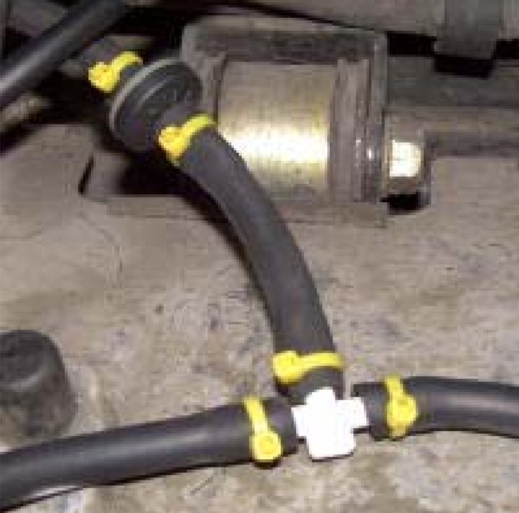
Simply press fitting the vacuum hoses onto the fittings may allow inleakage of air into the vacuum system, and thus reduce the vacuum power available to the servo. Use either vacuum clamps or silicon sealant on all joints. Cable ties pulled tight may be used as inexpensive vacuum clamps. If adhesives are used, apply them only to the fittings and not the hoses, so that the hoses do not become accidentally sealed shut.
Make sure that there is sufficient slack in the vacuum tubing and that it doesn’t interfere with anything, or rub on any sharp edges. Trim it to length and attach it to one of the hose nipples on the previously installed vacuum canister. Attach the remainder to the vacuum canister’s second hose nipple. If there is an additional vacuum canister, run this line to it, otherwise, it will be attached to the port on the servo after that has been installed.
It is critically important that all joints in the vacuum system are tightly secured. Poor performance of the cruise control system may result from inleakage of air into the vacuum system!
Servo
Note added 12/29/01 – A ready-made vacuum canister may be purchased from JC Whitney. This VC is compact and provides all of the vacuum reserve necessary for the CCS100 on the PC800. An alternative method for installing the servo and JC Whitney VC together inside the left fairing is available here. [Editor’s note: the link is long since dead and I can’t find a copy of it anywhere.]
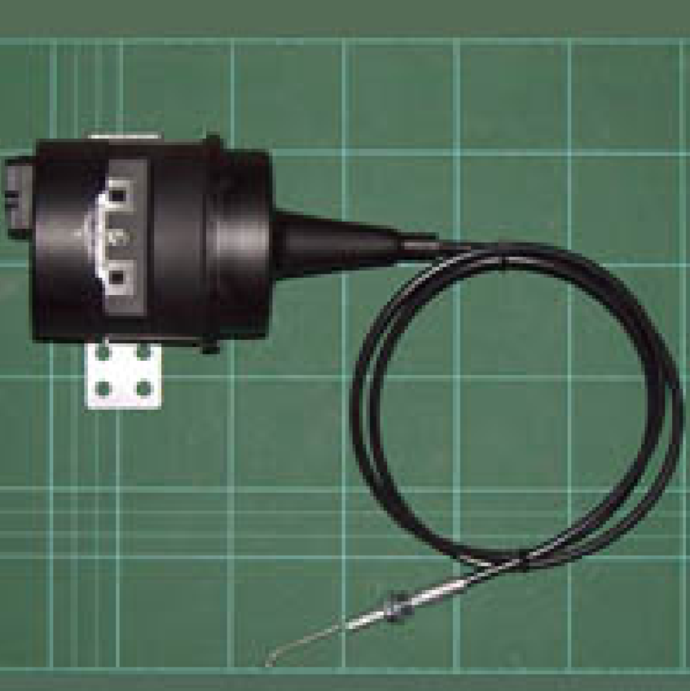
The servo is the electronic brains as well as the mechanical muscle of the cruise control system. It should be protected as much as possible from heat and electrical interference.
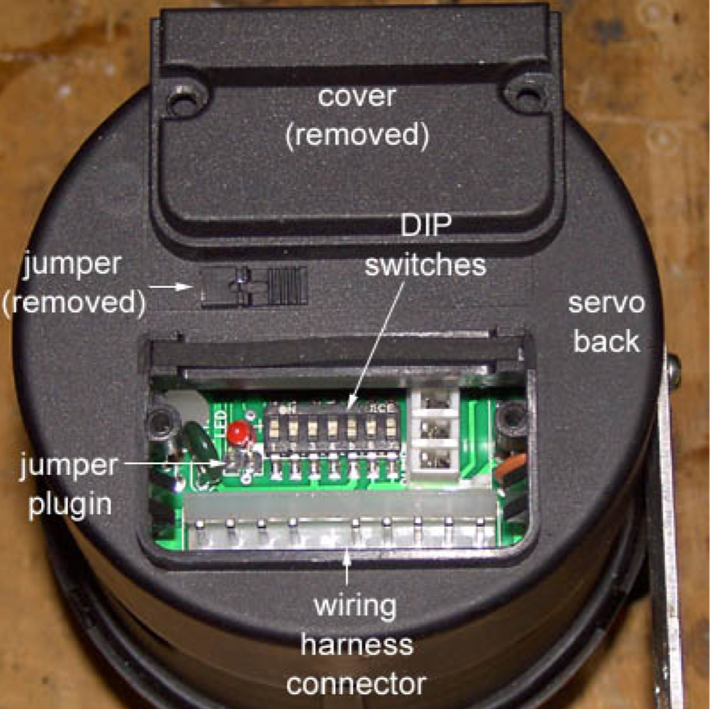
The servo sensitivity and other settings are set via the internal DIP switches. The degree of sensitivity needed for smooth operation of the servo depends upon the length of the bellcrank arm used to attach the servo actuator cable to the carburetor throttle linkage. If a rear-pulling actuator configuration is used, a long bellcrank may be installed, and the servo may be set to low sensitivity as the Audiovox installation manual suggests for light vehicles. But if a forward-pulling actuator configuration is used, the bellcrank on the throttle will necessarily be short in order to clear the engine shroud, and the servo will need to be set to high sensitivity to compensate.
Servo Setup
Remove the two screws from the access cover on the back of the servo. Inside the servo, remove the black jumper just below the LED and to the left of the DIP switches; this is necessary for using the cruise control with the PC800’s manual transmission. Set the internal DIP switches per the following tables:
| SW1 | SW2 | SW3 | SW4 | SW5 | SW6 | SW7 |
| ON | OFF | OFF | SEE BELOW | SEE BELOW | OFF | ON |
| 4000 pulses per mile | 4000 pulses per mile | Tach only | SEE BELOW | SEE BELOW | Control Switch Normally Open | Tach Source is Coil |
The sensitivity of the servo is set via switches #4 & #5.
| Vacuum Sensitivity | SW4 | SW5 |
| Low | ON | OFF |
| Medium | OFF | OFF |
| High | OFF | ON |
The choice of sensitivity settings depends a great deal on the length of the bellcrank arm, and the desired responsiveness of the system. The shorter the bellcrank, the higher the sensitivity needed to actuate it. Higher sensitivity settings require more vacuum since the actuator is required to move more frequently. Systems using short bellcranks of 1″ to 1-1/2″ may need the sensitivity set to “high”. Those systems with longer bellcranks that allow for full travel of the actuator will probably use “low” or “medium” sensitivity. It is suggested that the “medium” sensitivity setting be tried first for any new system design; adjustments to the sensitivity can then be made after system testing. Note that with higher sensitivity settings, there may be sharper throttle responses that could jerk the rider.
Attach the main wiring harness plug to the connector inside the servo. The gray and black pair of wires that are used for the magnetic drive line sensor will not be used and may be clipped off from the wiring harness. Reattach the access cover, making sure that the wires are laid out flat as the cover is tightened down.
Depending on the orientation of the servo when it is mounted, the curved mounting bracket may remain where it was installed by the factory, or it may be rotated 180° from its original position, or it may be removed completely..
If the servo will be mounted to the frame, two 3/4″-inch U-bolts can be used for attachment. But first, the bracket must have a couple extra holes drilled to match the width of the U-bolts. Clean off any burrs from the drilled bracket.
In installations where there is minimal room, as when installing extra-capacity vacuum canisters, it may be necessary to remove the servo bracket completely and secure the servo to the frame using large cable ties.
Servo Installation
The servo and vacuum canister have successfully been located in several different locations and orientations on the PC800. Two alternative mounting locations are discussed below.
Alternative 1: Right Roll Bar Cover (Fairing Protector)
Advantages:
- Very easy access to servo
- Easy to route actuator cable to throttle
Disadvantages:
- Electromechanical components are close to engine heat
- Servo may be subjected to road spray through openings in the cowl and fairing
- Tight space limitations
Inside the right roll bar cover is a limited amount of empty space into which the servo and a short vacuum canister can be fitted. Since this is right next to the engine casing, which gets quite hot, try to keep the cruise control hardware as far away as possible.
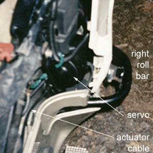
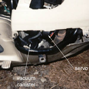
Above: Chuck Chiodini’s “Scooter” with servo and vacuum canister mounted inside the right roll bar cover.
Alternative 2: Left Front Upper Cowl
Advantages:
- Keeps electromechanical components away from engine heat, electrical interference, and road spray
- Substantial empty space for installing servo and vacuum canister
- Easy access to fuse block and electrical connections
- Easy to route actuator cable to throttle
Disadvantages:
- Most of bike’s forward plastic panels must be removed for servicing or adjusting servo
Inside the left front upper cowl is a great deal of empty space, and also two frame struts to which hardware may be secured.
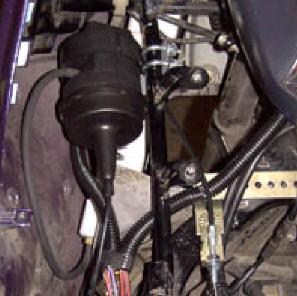
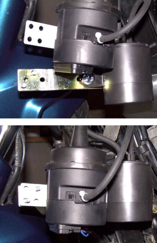
Here, the servo was mounted to the frame strut using the factory bracket and U-bolts. The white, twin-cylinder vacuum canister is mounted to the strut below.
The actuator cable has more length than is needed, so it must be routed in such a fashion as to use up some of its length. As the actuator cable leaves the back of the servo, it gently bends down and around to create a large 360-degree loop. This loop will be tucked inside the left front fairing and hidden when the Tupperware is reinstalled. Pass the cable over the frame towards the carburetor. Make sure that the cable remains clear of the steering head and forks. Loosely attach it to the anchor with its two hex nuts. It will need to be adjusted after the bead chain is attached between the actuator cable and bellcrank.
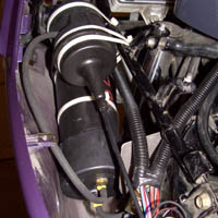
In the installation [above], the factory bracket was removed from the servo to minimize space, and the servo was mounted to the upper frame strut with large cable ties. Extra space was required to accommodate the extra-large, black ABS vacuum canister mounted to the strut below.
It is important to avoid tight bends in the actuator cable. The cable has more length than is needed, so it must be routed in such a fashion as to use up some of its length. As the actuator cable leaves the back of the servo, route the cable downward behind the left side body panel. Make certain that the cable will not interfere with the air duct/maintenance lid. Curve the cable back up toward the fuel filler box.
Finally, attach the vacuum line from the vacuum canister to the port on the side of the servo. Make sure that all vacuum connections are well sealed!
Throttle
Actuator Cable Anchor
The actuator cable must be anchored to a stable mount in which to pull the throttle against. There are two alternative methods for anchoring the cable: to the front, or to the rear. A rearward pulling cable will allow for the use of a longer bellcrank.
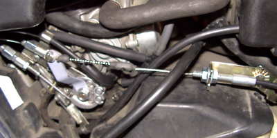
Alternative 1: Forward Pulling
Advantages:
- Easy to route actuator cable
Disadvantages:
- Awkward attachments of brackets to frame
- Mounting brackets can interfere with operation of throttle cables or choke cable
- Potential interference with carburetor airbox
The actuator cable needs to be mounted so that there is a long, unobstructed path between the cable anchor and the bellcrank on the throttle. The PC’s aircleaner box normally sits above the carburetors and is an obstruction that needs to be avoided. Consequently, for a forward-pulling actuator, the anchor point needs to be located far to the left of the centerline of the main throttle cables. There are few easy attachment points near where the actuator anchor needs to be mounted. Whereas it is possible to drill holes into the frame to which the anchor could be secured with bolts, this is not advised since this increases the risk of weakening the frame.
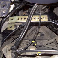
The CCS100 kit contains both straight and “L”-shaped brackets, either of which is long enough to extend from a pair of existing holes in the top of the frame near the steering head. The holes in these brackets will need to be enlarged in order to match the narrower spacing of the holes on the frame. Ensure that the throttle and choke cables are not obstructed or put into a bind.
The cable anchor itself is bolted to the bracket and should be pointed directly at the throttle bellcrank to minimize friction on the cable exiting the casing end. It is important to avoid tight bends in the actuator cable.
Note – with the servo cable extended to the right, and with the servo’s vacuum nipple facing you, the curved metal mounting tab should be at the rear and extending upward from the servo. As it comes from the factory, the tab extends downward. The tab should be unscrewed from the servo, reversed, and reattached.
Alternative 2: Rear Pulling
Advantages:
- Easy to route actuator cable
- No interference with throttle cables, choke cable, or carburetor airbox
- Anchor easily attaches to trunk release bracket
Disadvantages:
- None identified
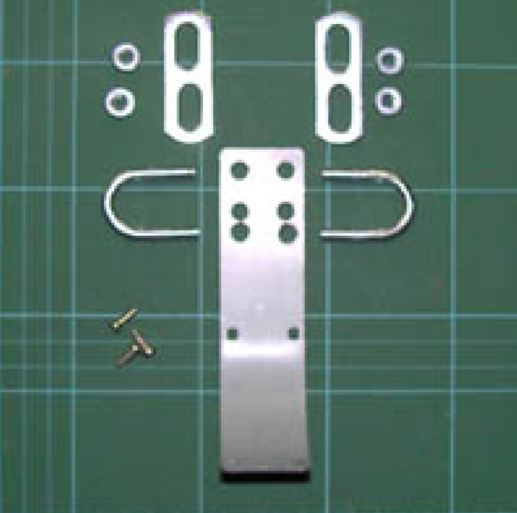
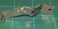
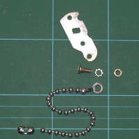
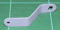
Shorten the anchor bracket so that it has only three open mounting holes. Make opposing double bends in the bracket so that the anchor’s position will be offset outwards by about an inch. The unused mounting ears on the side of the anchor may be left alone, or they may be cut off as in the picture at left. Angle the anchor downward slightly on the bracket, and securely tighten the bolt, lock washer, and nut.
Carburetor Connections
A connection to the throttle linkage on the carburetor is needed for the servo actuator cable to pull upon. This may be done with a “bellcrank”, which is an extension arm attached to the throttle. The cruise control installation manual says to “match the actuator pull to throttle travel, so to be greater than 40 mm, but less than 45 mm, to avoid a condition where the actuator is pulling past the full throttle stop and introducing the possibility of damaging the linkage.”
Alternative 1: Downward Bellcrank For Forward Pulling Actuator
Advantages:
- Short design is less susceptible to bending
- Full 50º rotation of throttle pulley
Disadvantages:
- Provides less than the recommended 40-45 mm throw of CC actuator cable
- Short throw requires the use of a higher vacuum sensitivity setting, which may result in sharp throttle responses that could jerk the rider.
- Actuator must pull harder to achieve the same throttle rotation as a longer bellcrank
- Potential for actuator cable or bead chain rubbing or snagging on engine shroud
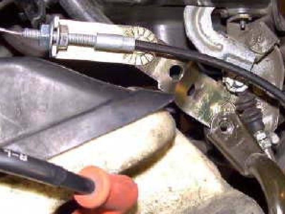
To accommodate the forward-pulling actuator, a bellcrank attached to the throttle must extend downward. Because of the limited space created by the engine shroud, the bellcrank cannot be much more than 1″ to 1-1/2″ inches long. Full rotation of the throttle is about 50º, so a 1″ (25 mm) bellcrank will have a throw of about 22 mm. Thus, full rotation of the throttle can be achieved, but only with about half the throw recommended for the CC actuator.
Reshape the “throttle mounting bracket (#28)” in the CCS100 kit. Cut it to length with a saw and rough shape with a bench grinder or file. Drill the mounting hole larger, and then shape with a small flat file to fit the flattened shaft for the throttle pulley. Use a round “rattail” file to make indentations to fit the projections on the throttle pulley. This makes for a very secure linkage by having the bellcrank closely fit around the throttle pulley’s projections.
On the side of the #1 (left) carburetor, remove the nut that secures the throttle pulley to its shaft. Attach the fabricated bellcrank to the shaft, then use a small amount of Locktite or blue RTV on the threads of the shaft, and secure the nut back in place. (Caution – do not get any thread locking compound on any of the bike’s plastic, as this may cause damage).
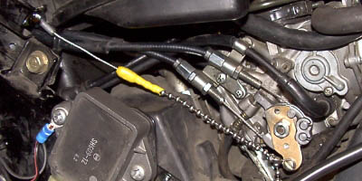
Anchor, forward-pulling actuator cable, and downward bellcrank [above].
Alternative 2: Upward Bellcrank For Rear Pulling Actuator
Advantages:
- Allows for recommended 40-45mm full throw of CC actuator cable
- Allows full 50º rotation of throttle pulley
- Cable and chain are not near anything to rub upon
Disadvantages:
- Must be bent around the choke cable, therefore design is somewhat weaker than a straight bellcrank
To form the bellcrank, start with a flat piece of metal 3-inches long by one-half inch wide. This will be bent into a dog-leg shape, as shown below:
On the carburetor above and behind the throttle pulley is the connection for the choke cable. In order for the bellcrank to miss hitting the choke cable, it is necessary to angle the bellcrank outwards from where it connects to the throttle.
The square hole that is filed in the lower end of the bellcrank is offset at an angle. This angle is not critical; an offset of anywhere from 15º to 35º is fine. It is okay to align the bellcrank to the throttle by “eyeball”, and cut the square hole to fit. Just make sure that there is enough movement to the throttle so that the actuator can not bind..
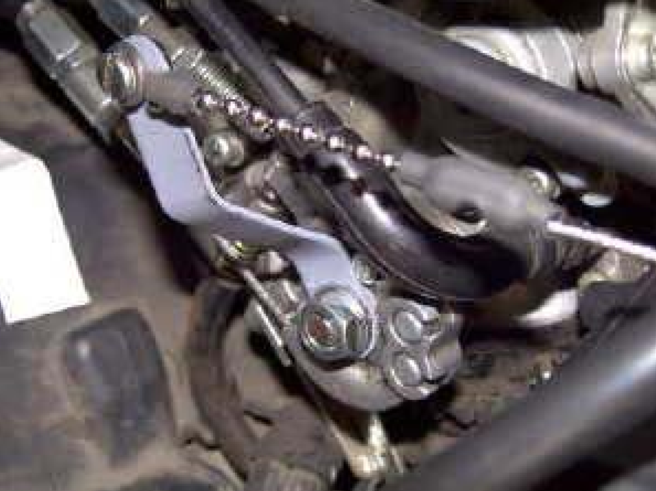
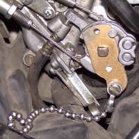
Upward bellcrank, rear-pulling actuator cable, and anchor [above].
Chain Connections
Locate the “bead chain eyelet connector (#25)” and “slotted head shoulder bolt with lock washer and hex nut (#34)” from the CCS100 kit. Attach the eyelet to the bellcrank using the shoulder bolt. Ensure that the bolt, washer, and nut are tightened securely.
Attach the bead chain from the servo actuator cable to the eyelet connector on the bellcrank. Adjust the attachment point on the bead chain to remove most of the slack from the chain and actuator cable, but leave a slight amount of sag. Too tight a cable will throw off your idle adjustment. Fine adjustments to the cable/chain tension may be made with the nuts on the actuator cable anchor mount. Once the cable/chain tension is correct, securely tighten the cable anchor nuts. Excess beads may be removed from the end of the chain. Pay attention to the note in the Cruise Control Installation Manual Insert regarding “safe bead installation requirements”; never have less than 7 beads in the chain. It is also important to ensure that nothing rubs, catches or chafes the action of the actuator cable and chain.
Reinstall the air box onto the carburetors, attach all connections, and tighten down all clamps. Make sure that there is no interference between the air box and any of the cruise control parts.
Electrical System
Disconnect the bike’s power before making any electrical connections.
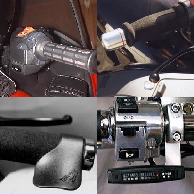
Handlebar Control Unit
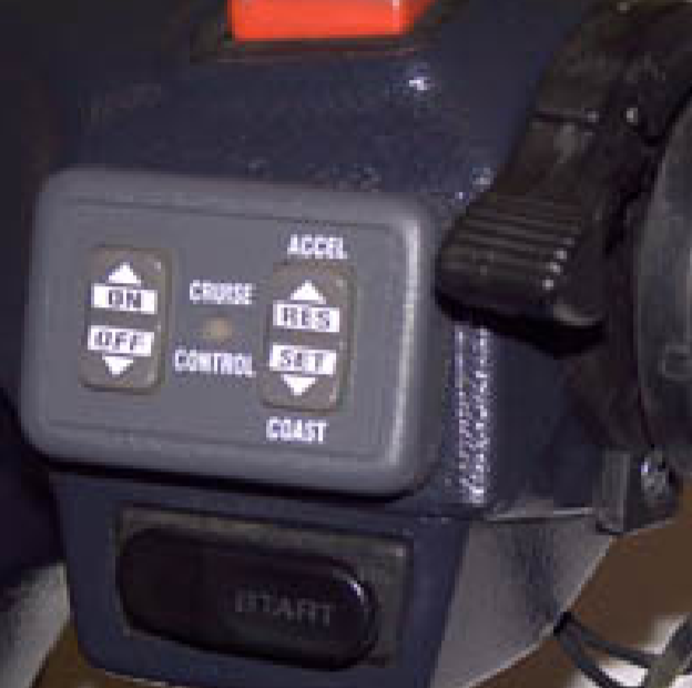
The kit’s “dash-mounted control switch”, as the name implies, is normally mounted on the dash of an automobile, but on the PC, an ideal mounting location is on the right handlebar in the space between the Run switch and the starter button. There are a couple of square inches of empty, flat space there into which the control switch easily fits.
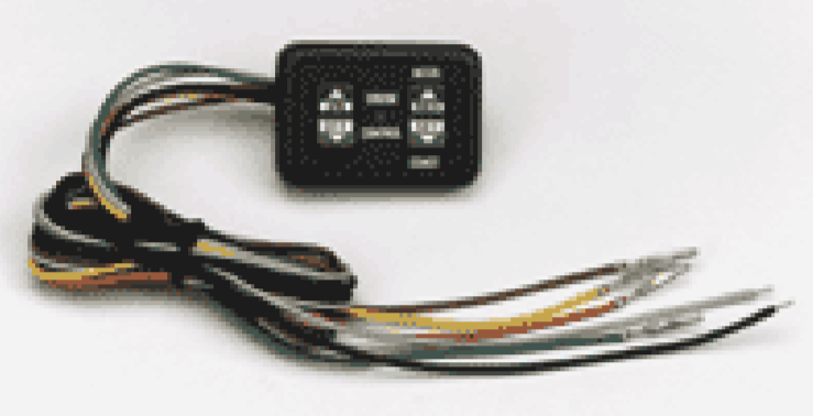
Using clear silicon sealant, seal the back of the switch box along the seams and around the wire hole to help seal out moisture out of the switch. Keep the sealant off of the removable backing for the adhesive. Let the sealant cure before mounting the switch.
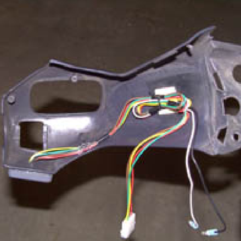
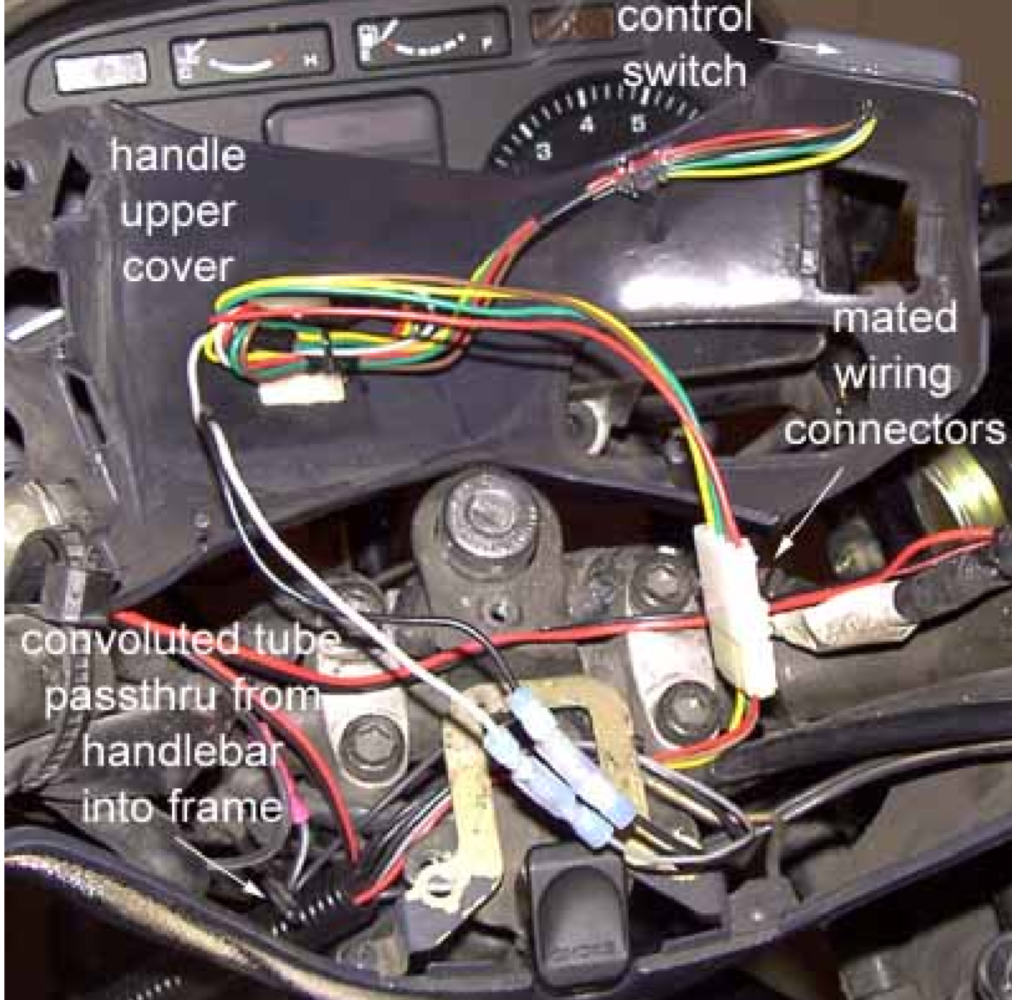
Place the template from the instruction sheet over the mounting space on the Handle Upper Cover and mark the plastic where the elongated hole needs to be made to pass through the wiring bundle from the control switch. You can either drill through the plastic, or melt through with a soldering iron. After the hole has been roughed out, clean it up with a file or a Dremel tool. Make sure that there are no sharp edges on the plastic. Pass the six wires from the control switch through the hole in the Handle Upper Cover. Peel off the backing from the mounting tape on the control switch, and carefully align the switch to the Handle Upper Cover and press the control switch into place.
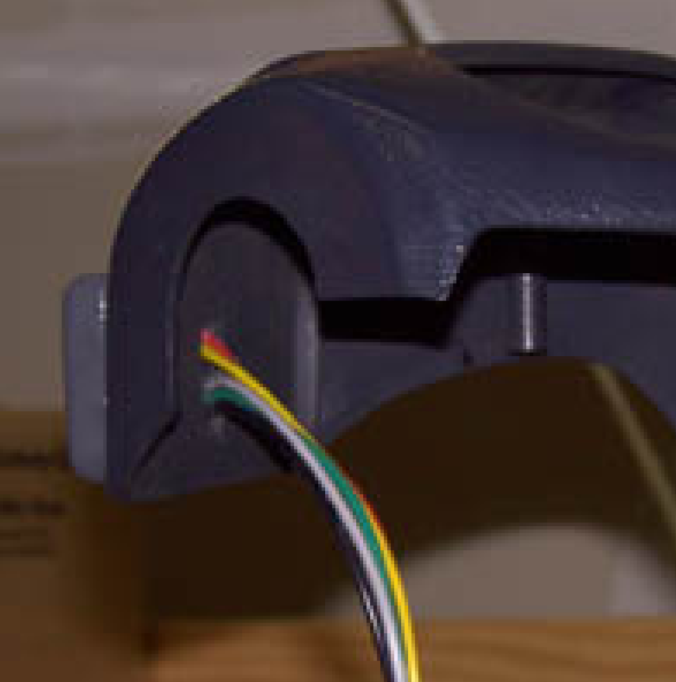
The wires may be secured to the inside surface of the Handle Upper Cover either by gluing them, or using cable ties with self-adhesive tie mounts. Take up the slack in the wires, but do not cut off the wire ends, because these have integral terminals which must be inserted into the connector.
Insert the four colored wire terminals (red, brown, green, yellow) into the supplied connector housing, following the color order guide that is attached to the connector. Bundle the excess wire and secure it with a small cable zip tie.
The black wire is a ground connection and is required to be connected for the CC to work. The grey wire provides power to illuminate the control switch; if you do not wish to have the control switch illuminated, you can leave the grey wire unconnected. Trim the black & grey wires to the same length as the other control switch wires, and attach quick disconnect terminals to them; either spade or bullet terminals are fine, just make sure that the appropriate mates are used later on the matching supply wires from the main wiring harness.
Main Wiring Harness
The main wiring harness connects to the back of the servo. The wires can all be covered with the black convoluted tubing to make a neat bundle. Route the bundled wires back along the left side of the bike towards the fuse block near where the left maintenance cover will be; make sure that the wires will not interfere with the placement of the maintenance cover and duct when it is installed.
Locate the brown, green and yellow colored wires. These must be separated from the other wires in the bundle and routed up into the Handle Cover where they will connect to the control switch wiring connector. The wires should pass up through the central opening in the Handle Lower Cover that is still mounted to the handlebars. Route the wires to the right handle to meet up with the wiring coming from the control switch.
Locate the connector housing with a single red lead and in-line fuse already in it. Insert the three colored wire terminals (brown, green, yellow) into the connector housing, following the color order guide that is attached to the connector. Route the red wire from the connector back so that it follows exactly the same route as the brown, green, and yellow wires; these wires may be covered with a section of black convoluted tubing to protect and conceal them where they pass from the bike’s body up into the steering handle covers.
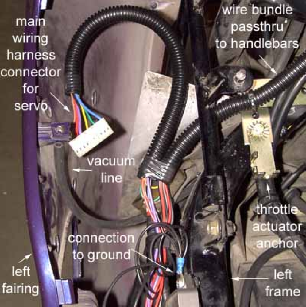
Splice a wire into the parking lights wiring to supply power for the handlebar control switch (grey wire). Make a connection to ground for the control switch, too (black wire). Route these wires through the convoluted tubing up into the handlebar covers. Attach terminals to these wires to mate with those from the handlebar control switch.
Join the connectors for the red, brown, green, and yellow wires from the main harness and the control switch in the Handle Upper Cover. Connect the grey and black wires, too.
Reattach the Handle Upper Cover, making sure that all wiring is clear of obstructions.
Wire connections
Brown, yellow, and green wires from control switch and servo: join matching colored wires together via connector plugs.
Black wires from servo and control switch: Connect to ground
Fused orange wire from control switch: Connect to any switched power that is conveniently available.
Grey wire from control switch: Connect to any fused, switched power that is conveniently available, such as that for the parking lights.
Red wire from servo: Connect to the black/brown lighting wire exiting the fuse box on the bike’s left side.
Blue wire from servo: Connect to the blue/yellow wire on the turquoise spade on the lower coil on the left side of the bike.
Purple wire from servo: Connect to the green/yellow wire in the rear brake light wiring bundle located on the forward side of the left trunk. Note – this wire will normally exhibit low voltage (8-9 volts) coming from the servo. This is a safety feature that allows the servo to sense that the brake lights are intact. If the servo cannot sense current flowing to ground through the brake light bulbs, it will not allow the speed control to be activated. Certain brake light modulators may have an effect on the operation of the servo’s brake light sensor.
Check all wiring for proper routing, avoiding chafing, moving parts, hot engine parts and any of the four sparkplug wires. Wire bundles may be secured into lengths of convoluted tubing to make for a tidy appearance and to protect the wiring.
Afterward
Reactivate the electrical system.
Replace the body parts.
Test ride.
Each time the ignition switch or the cruise control switch is turned OFF, the system is deenergized. To reenergize the system, the ignition switch must be turned on, and the cruise control switch must be moved to the ON position. The cruise control switch can be left ON at all times without causing any damage to the system.
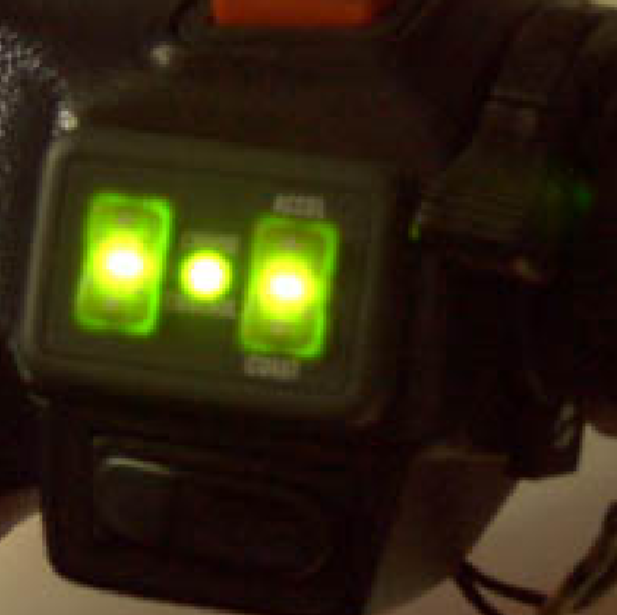
ON/OFF
Move the ON/OFF switch to the ON position. The light in the center of the cruise control switch will illuminate. This prepares the system for operation.
SET SPEED
After turning the system ON, wait at least 3 seconds before attempting to set your speed. To operate the system, drive the vehicle at a steady speed above 35 mph. Press the SET/COAST switch and release it, then slowly relax the throttle. Your SET SPEED is now programmed into the cruise control’s memory, and your driving speed should remain within 2 mph of your set speed. If you want to increase your speed, simply advance the throttle. When you release the throttle, you will return to your original SET SPEED.
ACCEL
You can increase you SET SPEED using the RESUME/ACCEL feature. Your vehicle will accelerate as you hold this switch to the RESUME/ACCEL position. When you release the switch, your SET SPEED will be reprogrammed to the present speed of the vehicle. You can also increase your SET SPEED gradually by quickly pressing and releasing the RESUME/ACCEL switch; each time you press and release the switch, your speed will increase by approximately 1/2 mph.
COAST
To reduce your SET SPEED, press and hold the SET/ COAST button. This erases the previously programmed SET SPEED, and allows the vehicle to coast. Just before slowing to the speed you want, release the button. Your present speed will be reprogrammed as the new SET SPEED, providing the vehicle is traveling faster than 35 mph. You can also decrease your SET SPEED gradually by quickly pressing and releasing the SET/ COAST switch. Each time you press and release the switch, your speed will decrease by approximately 1/2 mph.
RESUME
Whenever you use the brakes to slow or stop the vehicle, the cruise control will disengage but retain the programmed SET SPEED. To return to the SET SPEED, accelerate to a speed above 35 mph, then press and release the RESUME/ACCEL switch. The vehicle will automatically accelerate to the programmed SET SPEED, and hold that speed. When using the RESUME feature, you should be in the correct gear for your SET SPEED.
DISENGAGE
You can disengage from the SET SPEED in several ways:
- Gently tap the brakes to activate the brake lights.
- Turn the control switch to the OFF position.
- Press the clutch. This will cause the engine to rev slightly before disengaging.