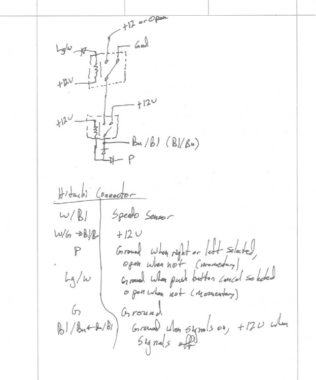
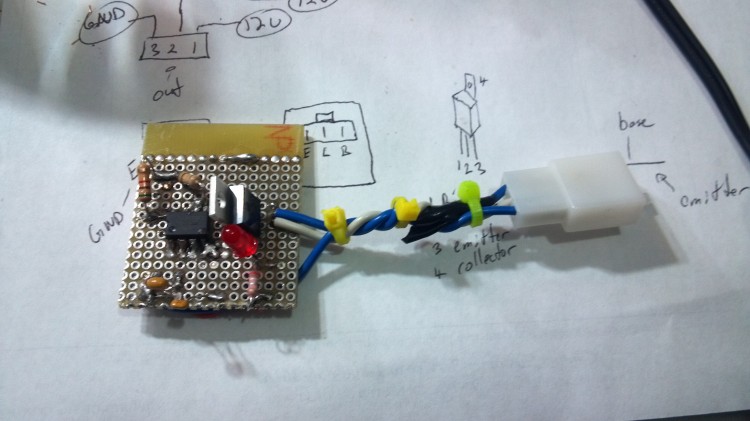
It is a good circuit that should work as intended. I however decided that I only wanted to tap into the harness in one location and built the below circuit.
This circuit is designed to tap into the harness only at the place where the cancel control unit connects. In order to do this, you will have to cannibalize your existing cancel unit for the connector or splice a new connector into the harness. If you have a still functioning cancel unit, I would suggest splicing in a new connector to the harness and saving the cancel unit and harness connector in case a future owner of your bike or another member of the IPCRC could make use of it. Those self cancel control units are expensive and hard to come by!
Note that the “+12V or open” segment of the circuit was left “open” on my final design. I would suggest that you do the same on yours.
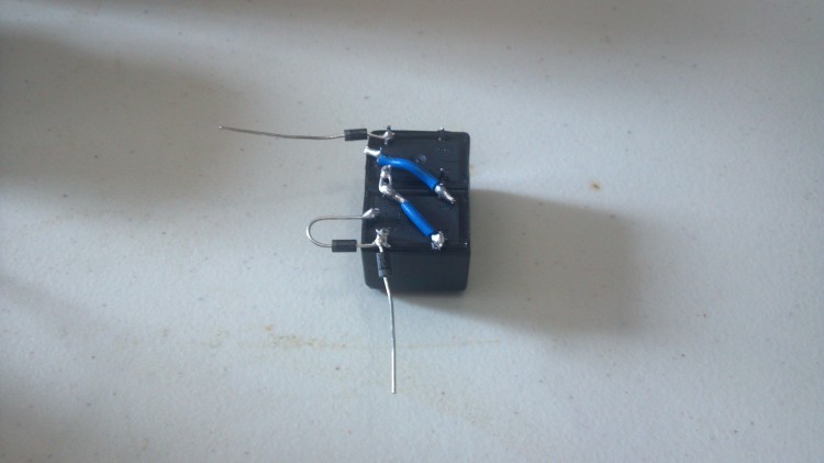
The circuit I designed works as anticipated. I used 1N4002 diodes from Digikey and JSM1-12V-4 relays also from Digikey. I used electrical tape to tape the two relays together with their pins facing up then I soldered the appropriate jumper wires and diodes in place, and then covered the whole thing with more electrical tape. The whole package takes up about 2x2x1 inch of space with a pigtail coming out one side that goes to the connector which plugs into the harness.
This is a picture of the relays taped together and the various bits soldered together. After this photo I added the wires that connect to the harness via the 6 pin connector cannibalized from the self-cancel control unit. For some reason I forgot to take a picture of the completed unit. Perhaps I will add a photo of that later on if I remember to take a picture…
In conclusion, either of the two above circuit designs will bypass your self-cancel control unit. If you do this, PLEASE save the cancel unit in case someone else on the IPCRC could use it. Also if you screw your electrical system up following these schematics, it’s not my fault! 🙂


