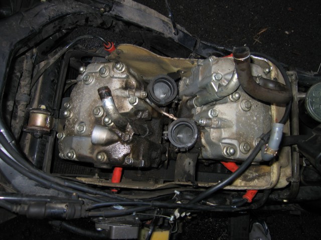
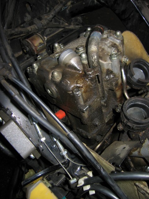
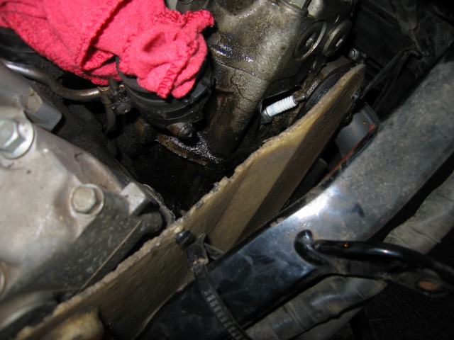
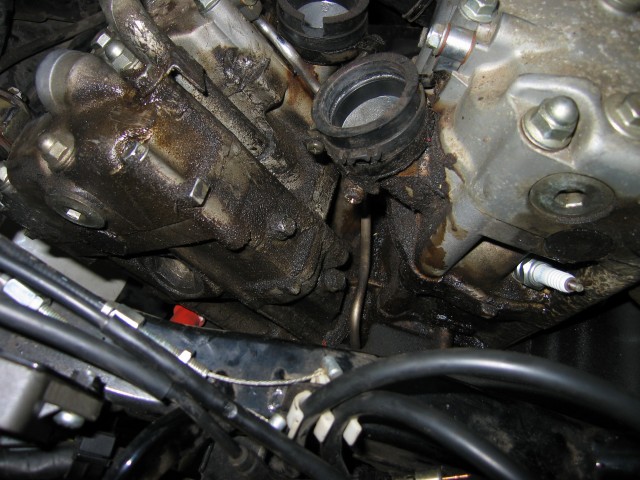
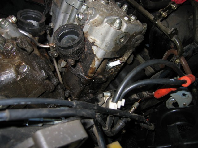
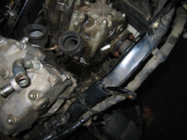
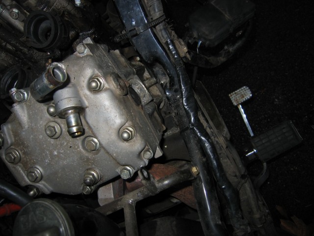
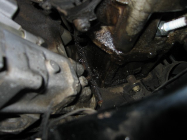
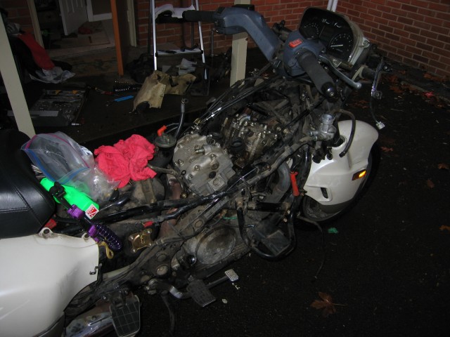
Have you ever wanted to install a battery disconnect switch on your motorcycle? No? Neither did I until I saw a picture of what happened to “White Satin” [Editor’s note: as of early 2020, the original group on Yahoo was moved to Groups.IO but we didn’t retain all of the old information. However, some of the oldtimers on the group will remember this story.] when some joyriders got hold of it. My first thought was to install a battery disconnect switch. No juice means no starter means either the thief has to push-start the bike (difficult but not technically impossible and something the typical joyrider probably wouldn’t do) or needs a truck and several strapping accomplices to pick it up (unlikely). Thus this project was born.
SAFETY NOTE: All photos, text, innuendos, and anything else on this site could easily kill you, make your dog three legged, blow up your motorcycle, maim an entire school bus full of kindergarteners, not to mention void any and all warranties within 1000 yards. I can’t be held liable for anything you do or do not do based on what is on this site. Everything is done at your own risk and at your own peril. Your mileage may vary. Don’t do this unless you know what you are doing. In fact, back away slowly from the internet and go read a good book. Or take a walk in the park. Or ride your motorcycle.
Now that the warning is out of the way… A quick synopsis:
This project installs a battery cutoff switch in the trunk of a Honda PC800 Pacific Coast. It disconnects the positive terminal of the battery from the bike’s electrical system. The entire project took me half a day, most of which was spent running around town for parts. The switch cost about $30, the battery wire cost about $5, the lugs and misc bolts cost around $10. You will need a hole saw, a file, a 1/4″ drill bit, an electric drill, a soldering iron or large crimping tool, and some luck. Now that you know what’s involved, read on to see the saga unfold!
The first step to this project was finding a suitable battery cutoff switch. Rather than buy an automotive unit, I opted for a marine grade cutoff switch. This was mainly due to looking in a marine catalog for an auxiliary fuse panel (more on that in another future post) that marine supply stores often carry. One thing led to another and I ended up ordering a Blue Seas Systems battery switch with key (P/N: BLU6005). I chose this one over the many other options from Blue Seas Systems and elsewhere because the price was right and I thought the key might be a nice feature. In hindsight I wish I had gone with a non-keyed version. The key sticks out into the trunk a bit much.
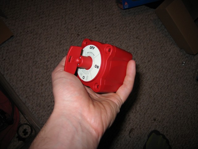
After a week of waiting the local marine supply store had my order in. Here it is in all its glory. The thing was a wee bit bigger than I had imagined. And I had already paid for it and couldn’t return it. Oh well I guess I’ll make do!
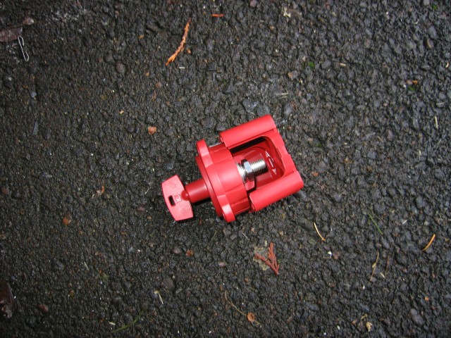
As I was fiddling with the switch I discovered something useful. The plastic cover on the rear of the unit detaches. That shroud is very useful in a marine application where there is a lot of salt spray coming in from three sides. Since it will be hidden under the PC800 plastics, it probably doesn’t matter as much. Well, at least I hope it won’t matter as much.
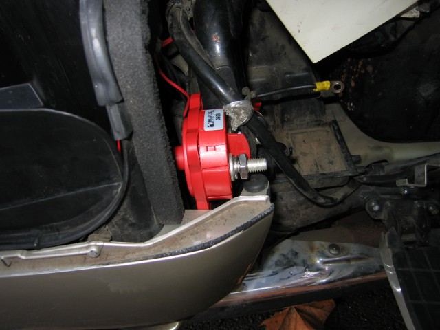
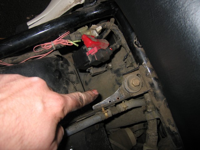
Since the battery is on the ride side of the bike near the trunk, and not wanting to slice into the plastics, I decided to try and mount the switch in the void between the plastics and the trunk. This is the first test fit before I cut any holes. Using a very accurate measuring device (my finger), I determined that the terminals would fit behind the plastics and not interfere with anything.
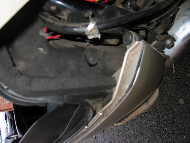
The next step was to start cutting into the trunk. Now before you carry out this step yourself, you have to ask yourself: are you willing to compromise that nice water-tight seal? Are you willing to screw up a irreplaceable and priceless Honda Motorcycles artifact? If your answer is yes, then bring out the drill! In this photo you can see where I made a pilot hole indicating the center of the switch. To figure out where it should go, I jammed the switch into the space and used a sharpie (notice the black marking near the hole) to try and trace an outline around the nose of the switch. Not the most accurate method in the world but it works.
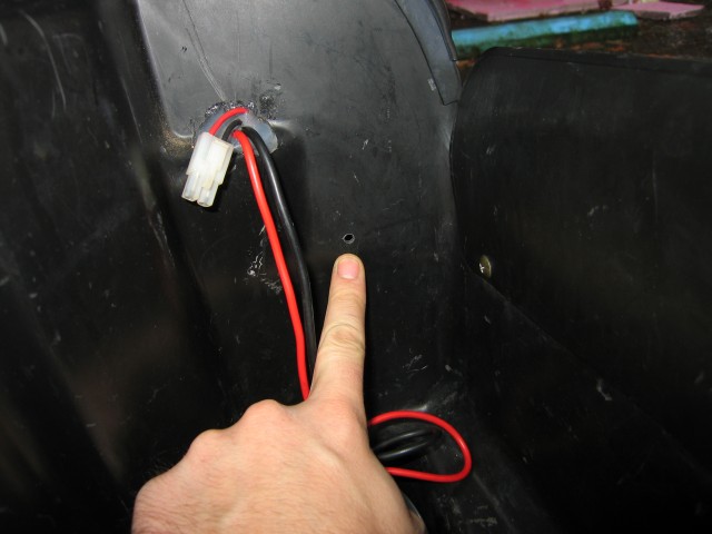
Here you can see the hole from the right side of the trunk. Those two sets of wires protruding into the trunk and sealed with clear RTV are for a battery tender and in case I ever need to jump the bike (or someone else’s) or if I have the charging system go out, have access to a car battery, and really need to ride somewhere. Ignore them for now.
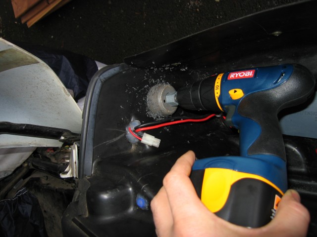
As you might have seen in the photos of the battery disconnect switch, it has a circular face that indicates where on and off are. The packaging indicated several ways to mount the device. I chose to mount it so that face is visible. It also makes it so the switch terminals don’t hit any of the bike’s tupperwear shell. This photo shows me drilling into the trunk using a hole saw. The face of the switch that I bought is 2.3 inches in diameter. My hole saw was slightly undersized. Due to some technical difficulties with my car (leaking antifreeze from the coolant reservoir), I opted not to go to the local home improvement store and find the right size. More on the ramifications of that in a few photos…
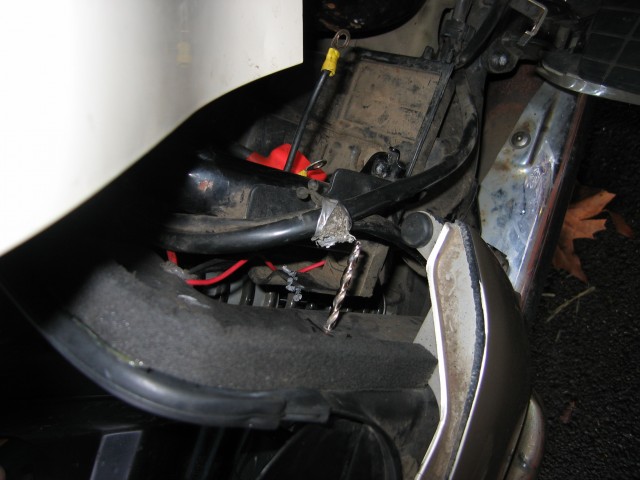
Pro-tip: while drilling the hole for the battery switch, do be careful of any wiring harnesses or other important bits that might be in close proximity. I caught this important tidbit of information just before I would have drilled through two rather important-looking harnesses.
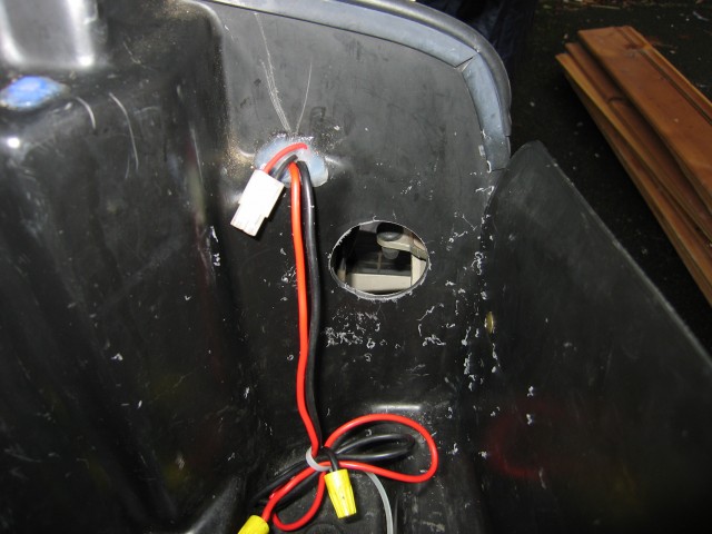
Here is the hole all cut out and pretty. However it is too small for the switch. The only way to get it to fit was to use a round file and slowly work away at widening the hole. After about a half hour of work (the home improvement store was more than a half hour walk away and doesn’t have bicycle racks), I had a correctly sized hole. It isn’t that pretty (as seen in later photos) but it works. If you are a neatnick, I suggest getting the right size of hole saw for the job. Otherwise work with what you have and make liberal use of RTV sealant (as seen in a few more photos).
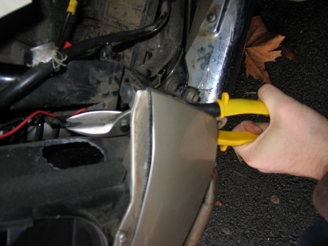
During my first test-fit I discovered that the battery box/trunk piece of plastic interfered a bit with battery disconnect switch placement. A bit of work with a tin snip and it was fixed. NOTE: I am damaging my plastics a bit in this photo. That bit of plastic connected to the trunk has a crack in it near the bottom of the photo that allows me to bend it like I am to get the tin snips in position. If you don’t want to have this fate befall your plastics (mine was already like this so no biggie for me), I suggest finding a better tool. Maybe a Dremel Tool with a cutting wheel or something similar. I didn’t have one so this is what I did.
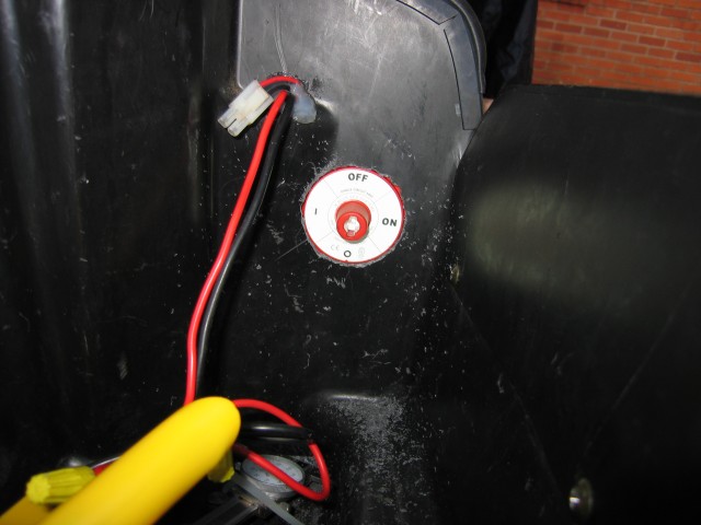
There it is all happy and in place! The myriad of plastic shavings is as a result of having to file the hole quite a bit to get it to fit. If you click on the photo to see the much larger-sized version of it, you can see that the hole isn’t the prettiest thing in the world anymore. It’s in the trunk though so hey, who’s ever going to know except me and my many thousands of internet Pacific Coast friends!

At this point in the process you have a choice to make. Either you can figure out how to secure the switch with just that one big hole (gorilla glue? zip ties? magic?) or you can drill four holes to run bolts through. I chose the later approach as it seemed more secure to me. Considering the terminals will be carrying 12VCD directly from the battery to the bike, it would be like an arc welder if the terminals ever came in contact with the frame of the bike. And considering that the battery is right there as is the gas tank, explosion could very well result. In this photo you can see the crude template I made to try and figure out where to drill the holes for the bolts. I used a 1/4″ drillbit I happened to have in the bottom of my toolbox.
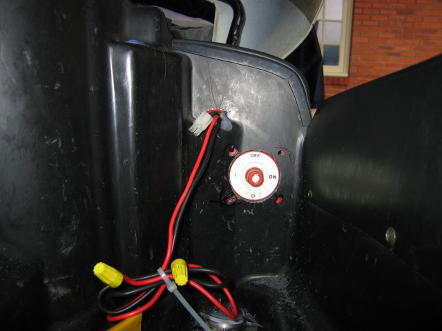
Here it is with the holes for the bolts drilled. They didn’t end up in quite the right spot so I wallowed the holes out a bit. More RTV sealant to the rescue! You also might notice some black sharpie marks near the holes. I first tried to guesstimate where the holes would be but decided that this would not be the best of approaches unless I wanted REALLY wallowed out holes.
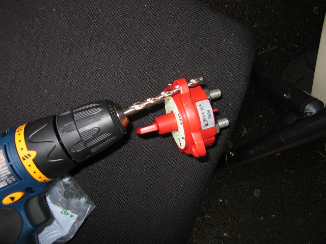
A quick run to the hardware store later and I had some nice M6 bolts, nuts, and washers. However the switch only has holes big enough for M5 bolts. Why would I buy too big of bolts? Because the nuts that the hardware store had for M5 were too small compared to the built-in retainers in the switch. Those retainers help to keep the nuts from spinning… at least at first. A bit of drilling out the plastic holes and all was right. I’m sure this just voided any warranty that came with that switch.
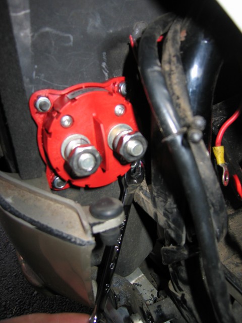
In this photo you can see me holding onto the nut from the back of the switch with a wrench. It was rather difficult to do this although necessary. I chose to use nylock-style (nylon inside the nut to keep it from backing off due to vibration or whatever) nuts. Those nuts have a lot of resistance to them. I ended up spinning the nuts in the pliable nut retention setups on the back of the switch. On the front side I used an allen wrench to get the job done.
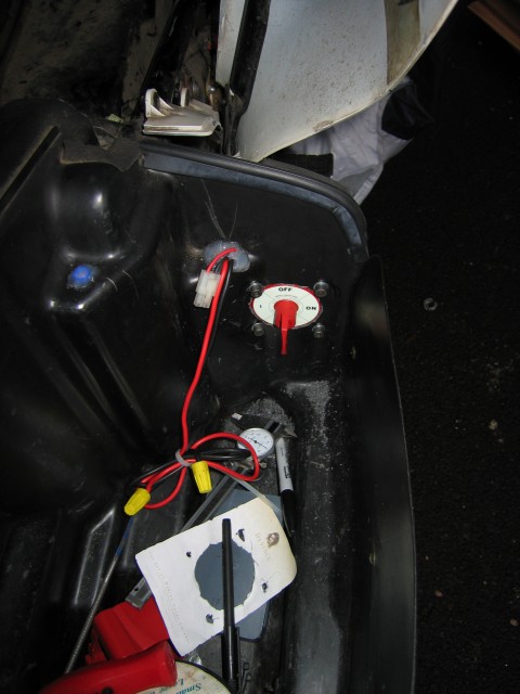
Here it is installed. Note that I used allen head bolts. In retrospect I wish I had gotten button head allen bolts or something similar. It probably would have looked a little nicer. Also I cut one corner that might come back to bite me in the trunk at a future date. Rather than buying stainless steel fasteners, I just used normal steel. Lets hope I don’t end up regretting that!
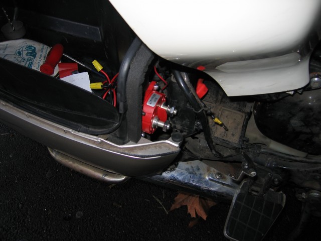
As you can see, it tucks nicely into that little space between the trunk, the plastics, and the frame. Like it was meant to be! Maybe the brilliant Honda engineers that created our bikes had even thought of putting such a device there. No, you’re right. They wouldn’t be that crazy.
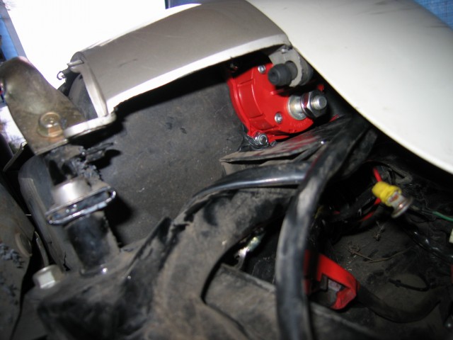
Here it is with the trunk closed. Nothing hits or interferes. Looks like we’ve got a winner! Plus in case the switch ever fails open and your trunk is broken, you can get to it to hotwire around it with only several pieces of plastic needing to be removed from the bike. For those of you worried that a thief might do this, I sorta doubt it unless he or she knows the PC800 plastic removal flowchart like the back of his or her hand.
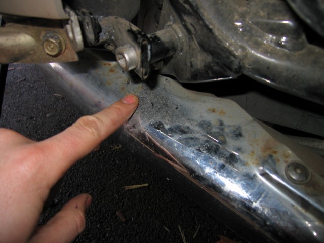
At this point I caught something very, very important. Se those little fine shavings of plastic sitting on the exhaust? Make sure to clean them off. Otherwise next time you warm up your bike you might get some plastic cooked on.
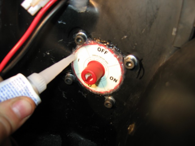
Next step: RTV the heck out of the hole! We all want waterproof trunks and the only way to try to assure that our trunks remain this way with this modification is through liberal use of silicone sealant. Of course who knows if it will really keep water out or not… the tube said “Water Resistant.”
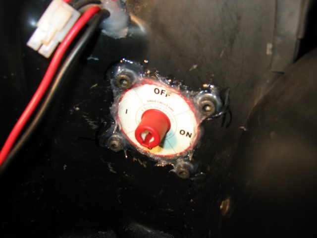
Here it is all caulked up. I put liberal caulking around the bolts as well as the switch. If you’re really paranoid (and have smaller hands than me), you can also caulk the switch from the back side. However I figured that was probably overkill.
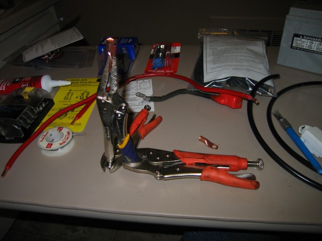
As you might have guessed, the stock battery cables on our bikes won’t work for this battery switch setup. Thus it’s time to make some new cables! The local auto parts store had a good deal on some 4 gauge battery wire (the red and black wire in this photo) and the lugs to put on the ends. I bought two feet of red and two feet of black. In hindsight, there was no reason for this project to need black wire. If anyone needs some black 4 gauge battery wire, let me know!
You might be asking yourself: what is that monstrosity in the middle of that photo? Three vice grips? What on earth is that for? Well my internet friends, that is my battery lug soldering station! I don’t have a table-top vice so I made one out of three vice grips. Before you go try this I should remind you that anything you do that is inspired or not inspired by me, my photos, this text, or anything else isn’t my fault. Of course if you make money off of it and want to give me some royalties, I won’t complain 🙂
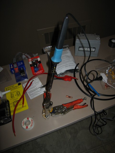
The guy at the local auto parts store is the one to blame for turning me onto the idea of soldering the lugs onto the battery wire. Evidently this is what they do for semi trucks and tractors. I thought I’d give it a shot since I don’t have a proper crimping tool for battery lugs and didn’t want to beat on them with a hammer. The PC800 has all crimped connections stock and there is general consensus in the automotive industry that crimps hold better over time than solder joints. In other words maybe you want to try crimping rather than soldering. I chose the more badass approach. Hence why there is a cheap hobbyist soldering iron sticking out of a copper battery lug held in place by three vice grips on a folding vinyl-covered table in my kitchen above the linoleum floor.
Yeah, I like to live dangerously. The vinyl-covered table sustained some nice solder burns as did the floor. Also I nearly set off the building smoke alarm system. At the last minute I realized the room was filling with blue smoke and popped open a few windows and doors. Be sure to do this in a well-ventilated area, boys and girls.

To determine when the battery lug is sufficiently hot enough to melt solder, touch a piece to the outside of the lug and see if it melts. As you can tell by the curl of smoke coming up from the burning rosin core, it is hot enough. At this point remove the soldering iron and fill the hollow part of the lug with solder. Oh yeah, make sure if you’re doing the solder method to buy lugs that have sealed pockets. Otherwise you’ll get solder all over the place. Once the pocket is full of solder, try and flick out the excess rosin now floating at the top of the molten solder with the tip of the iron. If memory serves (from a middle school electronics class), the smoke that the rosin puts out is toxic. As is the lead in the solder. Don’t let your kids to this step.
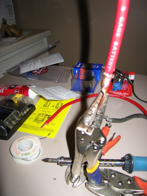
Now take your battery cable (make sure to pre-strip the wires back far enough) and shove it quickly into the molten solder. Actually before you do this with the real battery cable, try it out with a test piece first so you get the hand of it. When the cable goes into the solder, make sure it goes in all the way. I ended up having to reheat one of the lugs when the cable only made it half-way in. The solder should visibly flow into the copper wire. You might need to put more solder into the lug once the wire is in place. When in doubt, add more solder and more heat.
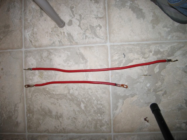
Here are the cables completed. Each cable has a small lug and a large lug. The large lugs are 3/8″ (If I remember correctly) while the smaller ones I eyeballed in the store. You might want to take actual measurements to make sure you’re getting what you need. Be sure the lugs match the bolts and the wire gauge. Oh, and you are probably wondering what lengths of wire I used. The tiles on the floor are 12 inches long. That should give you a rough estimate. I determined what length to use by stuffing the battery wire into the bike to see how long it needs to be. I marked it with a sharpie to cut it to length. The shorter cable will go from the cutoff switch to the main fuse/relay. The longer cable will go between the switch and the battery. I chose to make the wire longer than it absolutely needs to be so that it can be connected and disconnected with the battery most of the way out of the bike. We’ll see if that proves to be a good choice or not the next time I have to pull the battery out of the bike.
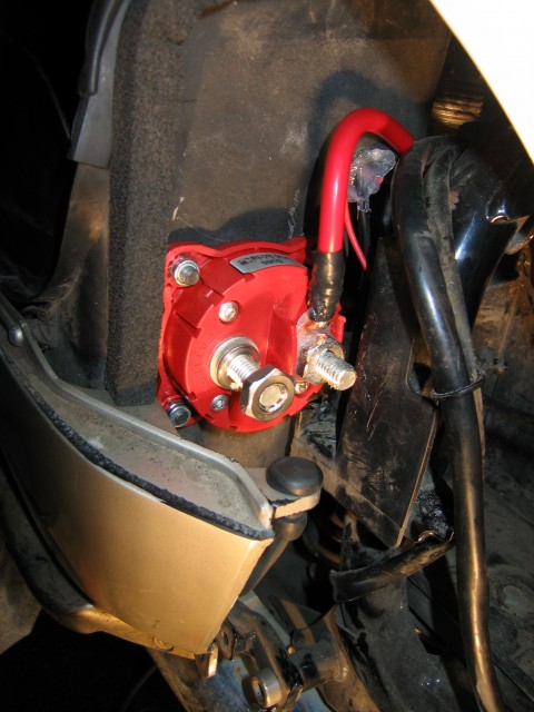
Here is the wire between the switch and the fuse/relay installed. I put some dielectric grease on the terminal and lug. I also added some electrical tape around the lug. Be sure to not let the dielectric grease to migrate between the two lugs. That would sort of defeat the purposes of the switch and potentially make it catch on fire.
UPDATE: I have been reeducated by a fellow member of the IPCRC. It turns out that dielectric grease is an insulator so no worries on having the grease short out anything. Also you don’t need it on this sort of terminal except for corrosion prevention. Here is some good information on dielectric grease. What I wrote before is funny enough (to me anyway) that I’m going to keep it and not change it, just post this update.
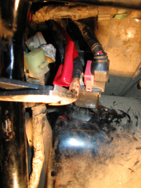
As I was getting ready to install the wire onto the switch/relay, I discovered that Honda made the place where the connection goes a bit too small for a normal lug. The lug that they used is correctly sized. The lug that I used didn’t fit. Thus I used a pair of dikes to cut the lug down to fit. It’s now more of a 3/4 ring connector… But it will work!
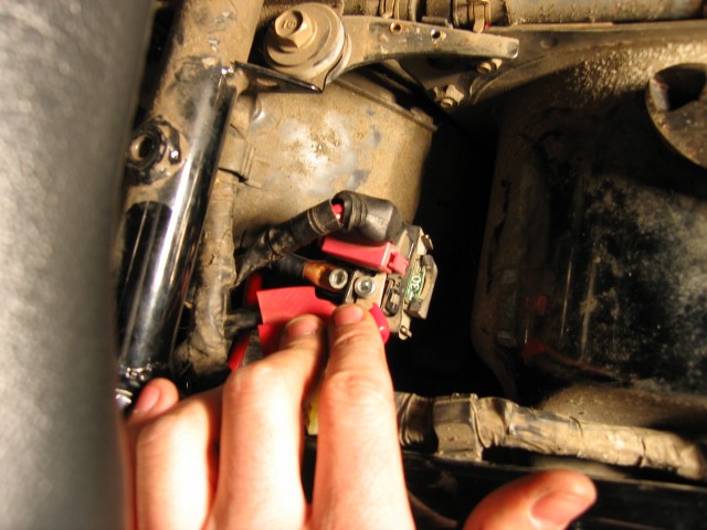
Here it is all wired into the fuse/relay. Make sure to align the wire so that the dust cover will still work. I’m not sure what would happen if that dust cover isn’t there but it would probably be bad news bears.
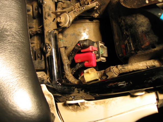
All done and in place. It almost looks stock! In the future I will probably be mounting an auxiliary fuse panel in the space next to the relay/fuse. That is for another day and another post though.
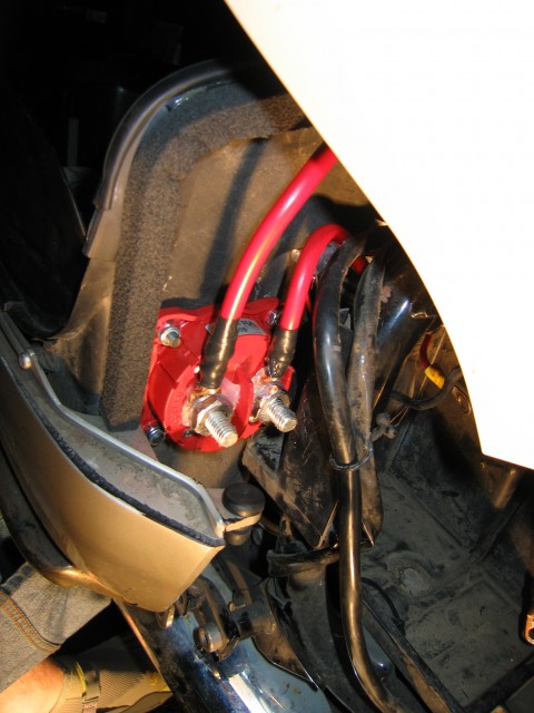
Here is the switch with the second wire (batter -> switch) installed. I also put some dielectric grease on that lug. Again, make sure the grease from the two sides doesn’t touch. I think the result would be something akin to what happened in Ghost Busters when the beams crossed. (SEE THE UPDATE ABOVE. NO BEAMS WILL CROSS.)
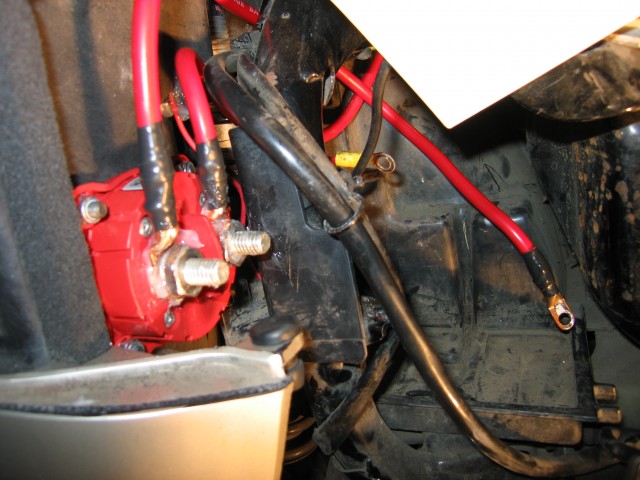
The cable that connects to the battery can be seen on the right side of this photo. Lots and lots of length to get that battery in and out.
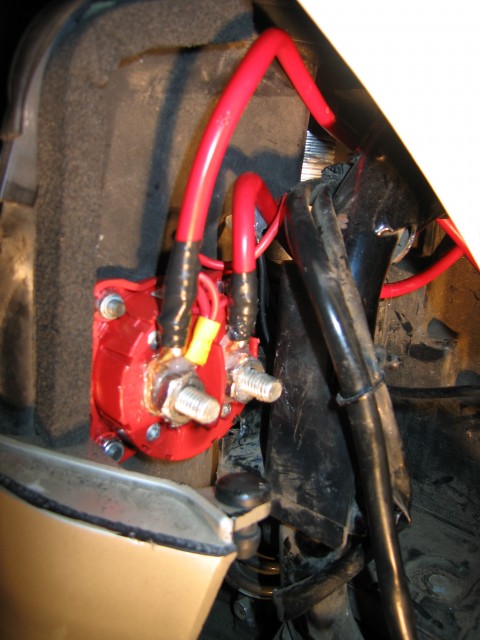
All installed and ready to go! You might notice a couple of smaller wires just sneaked into the battery side of the lug. Those go to a battery tender junior plug and a bare wire used for jump-starting that are hidden in the trunk. Depending on your setup and uses, you might want these wires connected on the other side of the switch. This is also where you would install an auxiliary tap to run a 12 volt clock or alarm system that needs a permanent connection to the battery. The lug on the switched side would be a good place to put a wire for an auxiliary fuse panel or a heat troller. No need to mess with directly wiring to the battery that way.
So there you have it folks. A step-by-step procedure on how to add a battery disconnect switch to your bike. Hopefully this will help someone from getting their bike stolen by joyriders. Maybe it will even save someone from draining their battery when the bike isn’t in use. It’s not like you really need that voltage gauge displaying the charge of the bike all the time anyway, right? If you do end up doing this mod, send me a photo or two and I’ll post them at the bottom of this page. Or for that matter, if you have any questions or comments, drop me a line in the comments section. Heck, if you need more photos of any of this let me know and I’ll see what I can do. Good luck and YMMV!

